Note: This prop replica is a self-made fan production. It is not for sale and I do not take commissions.
After almost 2 years of construction (2020-2021), my self-made TR-590 hero prop replica with electronics controlled by a Raspberry Pi Zero is now mostly finished. Apart from the capacitive touch keys, it has no other real sensors. But it has a working TFT screen and sound, and most LEDs are RGBW multicolor.
First demo video of my TR-590
Section titled First demo video of my TR-590I made a demo video of the current state with the electronics working. The software is still a work in progress and the labels need to be improved. Unfortunately, the capacitive touch pads in the upper section do not always react. The power management is also not reliable, LEDs sometimes flash oddly.
This video is also available on Vimeo.
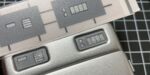
Image gallery
Section titled Image galleryI took some pictures from different angles, closed and opened, with electronics turned on and off. My custom replica is not screen accurate. The height of the main shell was increased by a few millimeters to create more space for the electronics. The front was modified and I used laser-cut acrylic greebles.


Currently used components and connections
Section titled Currently used components and connections- 3.7V LiPo with 2.000 mAh (approx. 6 mm thick, 66 mm length, 40 mm width)
- PowerBoost 1000C is boosting 3,7V to 5V (and charging the LiPo via micro USB)
- Micro USB socket at the bottom of the main shell to plug in external power (charging)
- Physical power switch to completely disconnect the battery from the PowerBoost
- LiPoPi circuit (left side of the breadboard) with a push button to power up or shut down the Raspi
- Raspberry Pi Zero (1st Gen.) with micro SD card
- USB sound card (PCM2704) connected to Raspi's USB test pins on the back
- TPA2012 Audio Amp connected to the USB sound card outputs
- Two small speakers connected to the TPA 2012 Audio Amp (stereo sound)
- Two MPR121 12-channel capacitive touch modules, connected via I2C
- ST7789 320x240 SPI TFT display, connected via SPI0
- TLC5947 24-Channel LED controller, connected via SPI1
- Rectangular RGB LEDs, connected to TLC5947
- Two DotStar 8×8 matrix boards, connected in series to TLC5947 (via SPI1)
- One 8xRGBW NeoPixel stick and 12 single RGBW NeoPixels, connected via GPIO12 (PWM0)
- Because of the many LEDs used, I also added a 1000 µf capacitor to the 5V line
- Two reed switch circuits to detect the status of the door
- One tiny push button behind the "EMRG" light in the flap door
Here's a wiring diagram of the latest version of my test rig.
Things still to do
Section titled Things still to do- Improve the user interface sticker of the main shell
- Improve the Python scripts and add more functions (LED sequences and animations)
- Check power management. The LEDs/NeoPixels sometimes flash oddly
- I am also concerned because the LiPo battery is placed directly on the Raspberry Pi Zero and the RasPi can get hot. Maybe it is better to add some kind of heat insulation between the LiPo and RasPi.