Disclaimer: I am not an expert in electronics or programming. That's the way I did it, and that's not necessarily the correct way to do it.
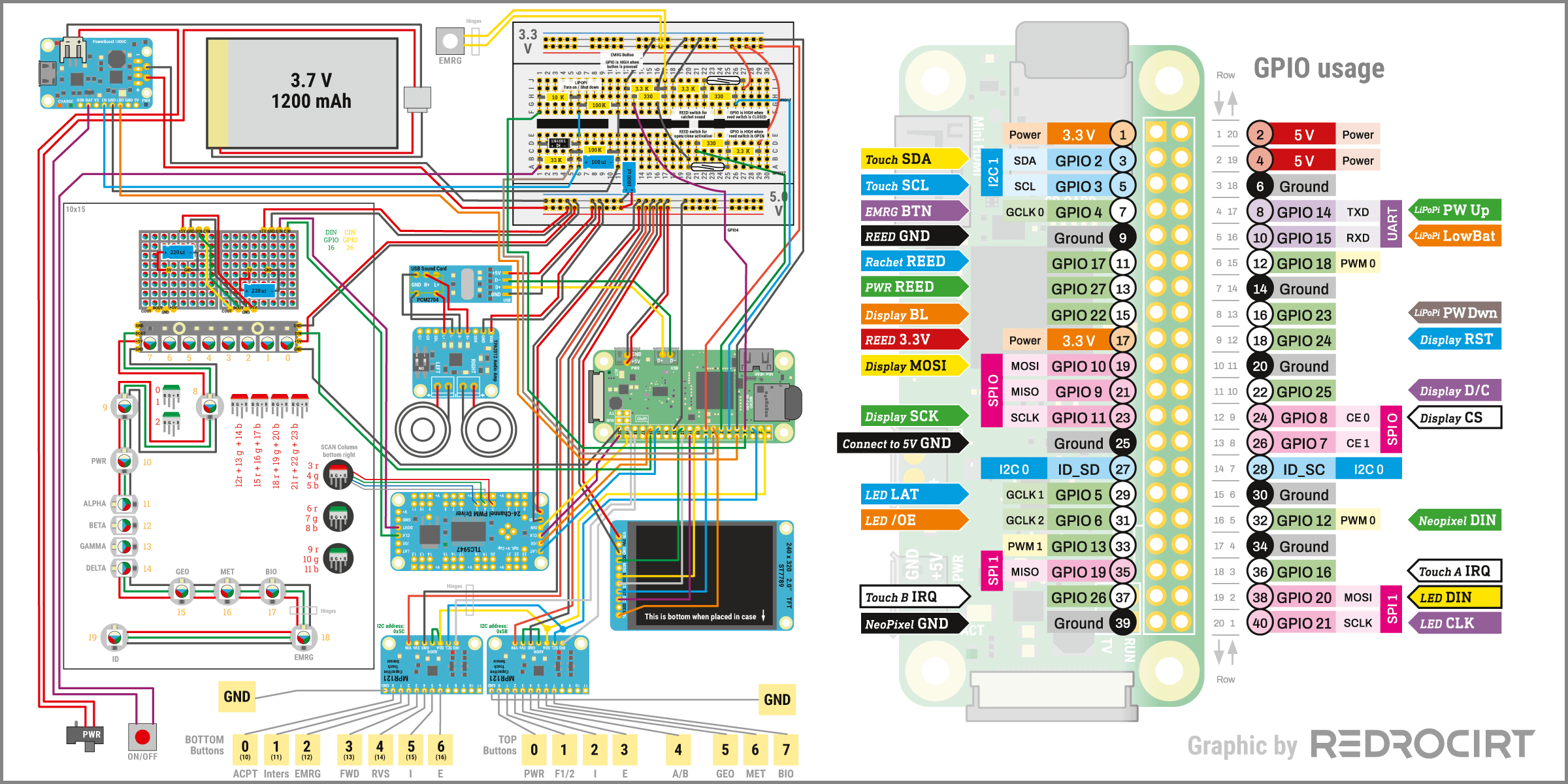
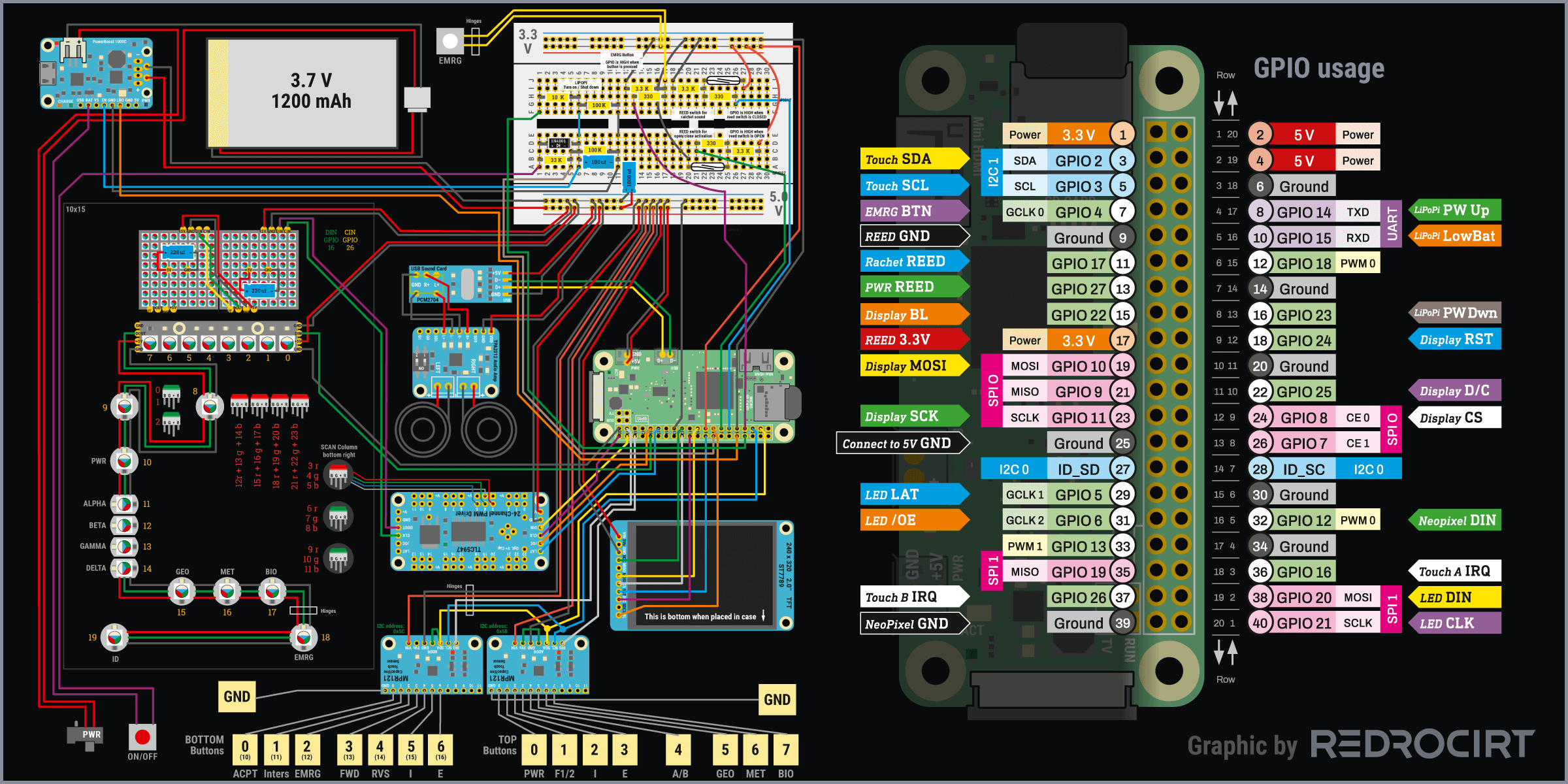
It's been a while since I updated the diagram for my test board, so here's a new version:
- Updated the NeoPixel chain to reflect the final order in my build
- Added the wires for the interrupt signals of the touch boards
- Added the circuit for the EMRG push button in the door
Note: It's recommended to use a logic level shifter like 74AHCT125 to boost Raspi's 3.3V GPIO data signals to 5V for modules that are also connected directly to the 5V power line. I didn't use a logic level shifter, but I should have (it worked without, but not reliably). Use a logic level shifter!
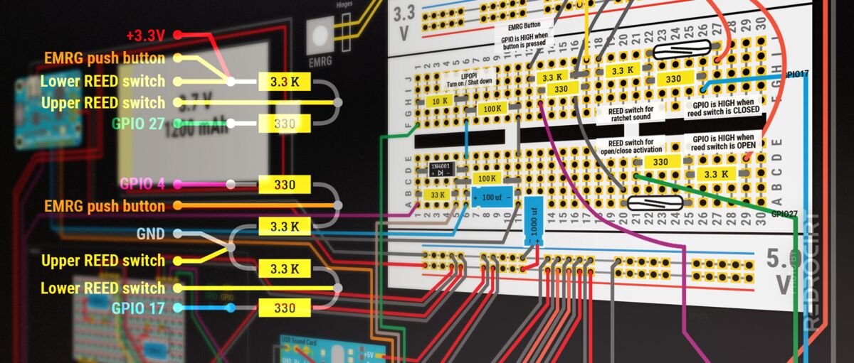
Compact resistors arrangement for 3 switches
Section titled Compact resistors arrangement for 3 switchesI have 2 reed switches to detect the status of the flap door, and a push button below the EMRG light in the door. As already explained, you should always connect switches to the GPIOs of the Raspberry Pi only in combination with resistors.
I used the following colors for the wires:
- Two yellow wires are soldered to the ends of the upper reed switch
- The upper reed switch gets connected to GPIO 27 with a green wire
- Two yellow wires are soldered to the ends of the lower reed switch
- The lower reed switch gets connected to GPIO 17 with a blue wire
- Two orange wires are soldered to the pins of the EMRG push button
- The EMRG push button gets connected to GPIO 4 with a purple wire
- All switches get connected to Raspi's 3.3V GPIO and GND (ground)
Since I only use off-the-shelf components (and thus only “regular”/large resistors with about 5mm length and 1-2mm diameter), I made some wiring diagrams to find a way to solder the circuits as compact as possible. The schematics shown below are basically all the same.
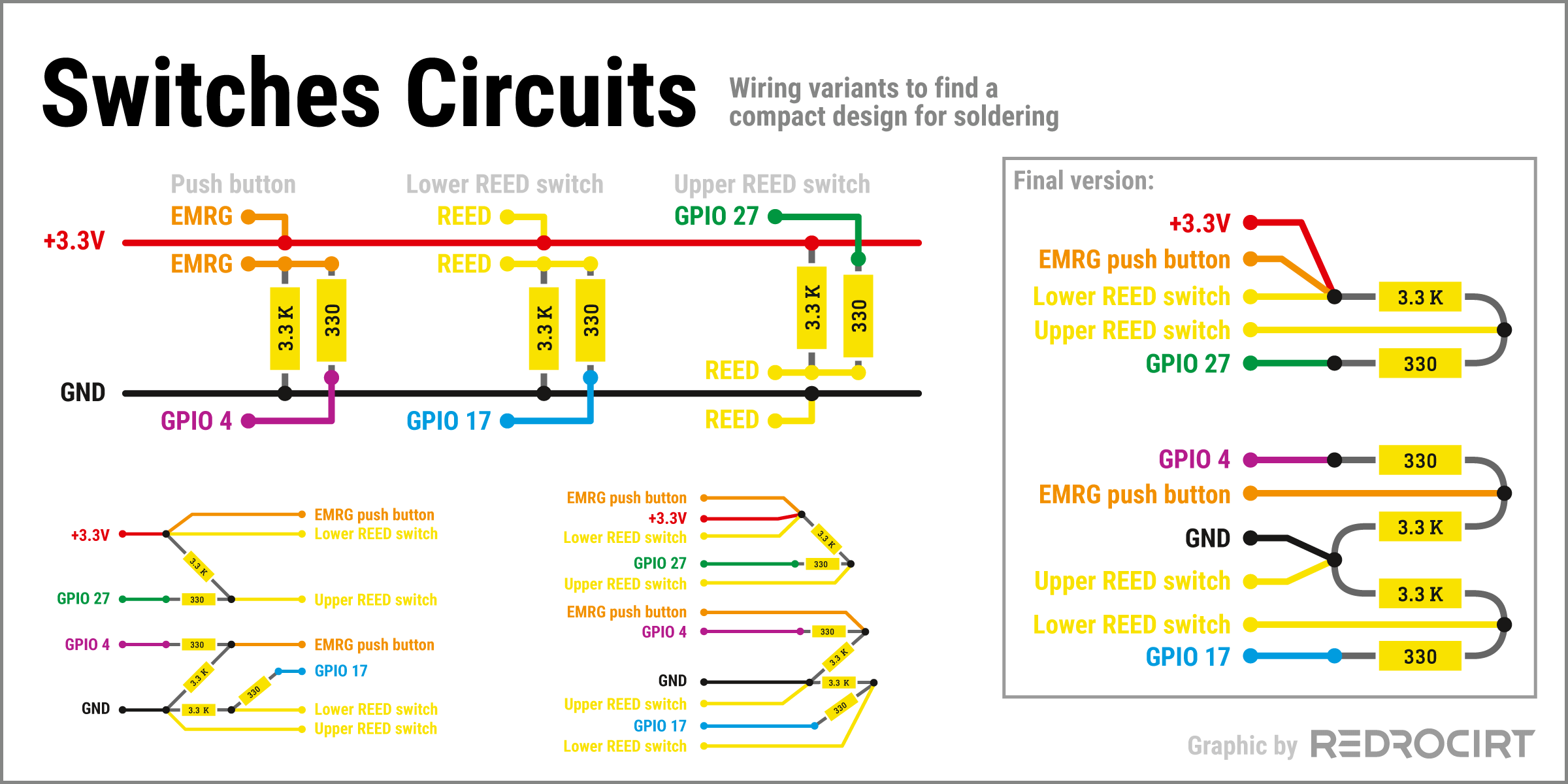
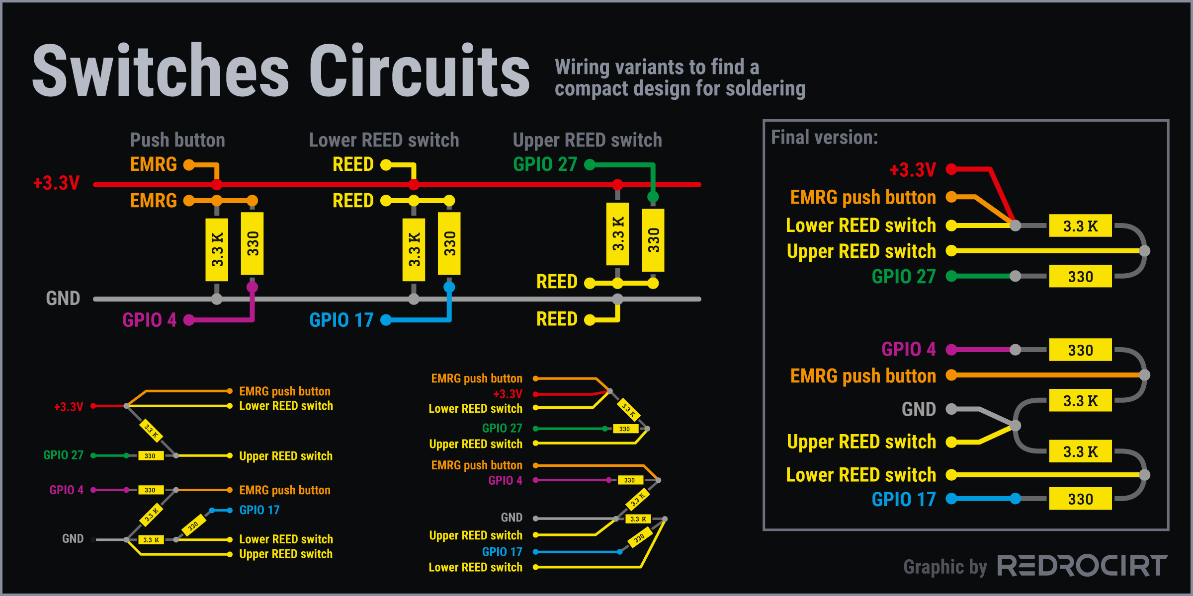
In the final version all wires come from one side and I shortened the metal pins of the resistors and bent them round with pliers. I ran the yellow and orange wires of the reed switches and the EMRG push button along the inside walls to the front area and glued them in place with epoxy.
Unfortunately, I forgot to take photos after I soldered the resistors and wires together. After soldering, I wrapped the resistors construction with electrical tape and also permanently attached it with epoxy glue.
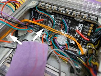
Orange wires = EMRG push button 
Yellow wires = REED switches 
Black clump = isolated resistors