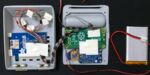
I wanted to power the Raspberry Pi Zero with a 3.7V prismatic (flat) LiPo battery. The PowerBoost 1000C module seems to be the way to go for portable Raspi projects. It provides ~5V boost output to power the Raspi and you can charge the battery via the micro USB adapter at the same time.
All that's missing is a push button to power up the Raspi or shut it down without connecting or disconnecting the battery. The Raspi is like a normal computer and should be shut down properly on button press to avoid writing damage to the SD card.
Power-Up/Power-Down on simple button press
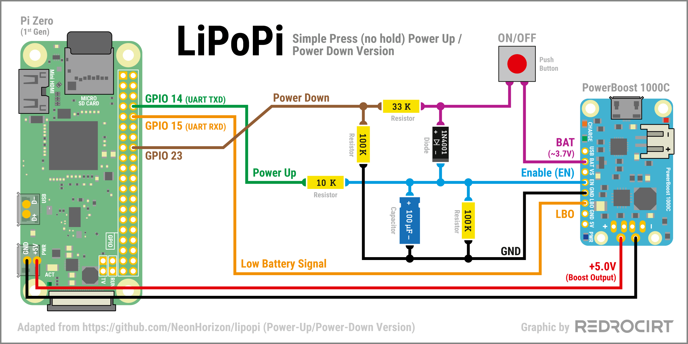
Section titled Power-Up/Power-Down on simple button pressFortunately, I found the great LiPoPi project on GitHub with instructions, schemantics and scripts:
github.com/NeonHorizon/lipopi
I decided to go with the "A Simple Press (no hold) Power-Up" (and Power-Down) version:
github.com/NeonHorizon/lipopi/ [...] power_up_power_down.md#a-simple-press [...]
... with a small modification:
Section titled ... with a small modification:At this time I didn't know much about "Neopixel" LEDs, I just knew that I might want to use them. In the wiring instructions for the LEDs I read that you should connect them to GPIO 18 (PWM output), so I modified the LiPoPi circuit and connected the "Power-Down" signal line to GPIO 23 instead of 18.
How does it work?
Section titled How does it work?- When the push button is pressed, the BAT output (3.7V) sets the EN pin high (enabled) and turns on the PowerBoost. It also charges the 100µF capacitor which holds the EN signal high for some seconds when the button is released (the capacitor creates a RC network in conjunction with the 100K pulldown resistor between EN and Ground). This is just long enough for the Raspberry Pi to take over, by pulling GPIO14 high during the booting sequence.
- The 10K resistor between GPIO14 and EN prevents GPIO damage (because 3.7V is present on EN line for a shot time when the push button is pressed, but hardly any current).
- The 1N4001 diode prevents that GPIO23 gets a high signal from EN while Raspi is on.
- GPIO23 gets pulled high when the push button is pressed again. The 33K and 100K resistors act as a resistive voltage divider to make sure the GPIO signal isn't above 3.3V, to prevent GPIO damage. This time, Raspi's boot sequence should be finished already, so it can react to the high signal on GPIO23 and trigger the system shutdown. This is done by the Python script lipopi.py. When the Raspi is off after the shutdown sequence, GPIO14 is low, as well as the EN signal. A few seconds later, when the capacitor is discharged, the PowerBoost turns off.
- The LBO (low battery) pin of the PowerBoost is connected directly with GPIO15. There are no resistors required, because the LBO signal will only be high when the battery is flat already, it supplies less than 3.3 V at this stage. When the signal on GPIO15 is high, the script lipopi.py triggers Raspi's shutdown sequence.
Compact arrangement for the parts
Section titled Compact arrangement for the partsIn my build I wanted to use mainly of-the-shelve parts. I didn't have a 33K resistor at home, so I used 22K+10K+1K in a row instead for my first test (and ordered 33K resistors for later test versions). I placed all parts on the table and tried to find a compact arrangement. The result looked... well, I just thought that's good enough for a first test.
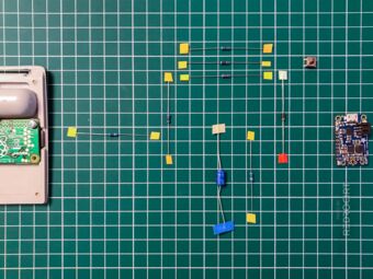
Parts arranged as in the schematic 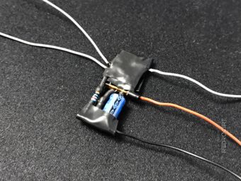
First LiPoPi test circuit 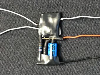
Covered by insulation tape


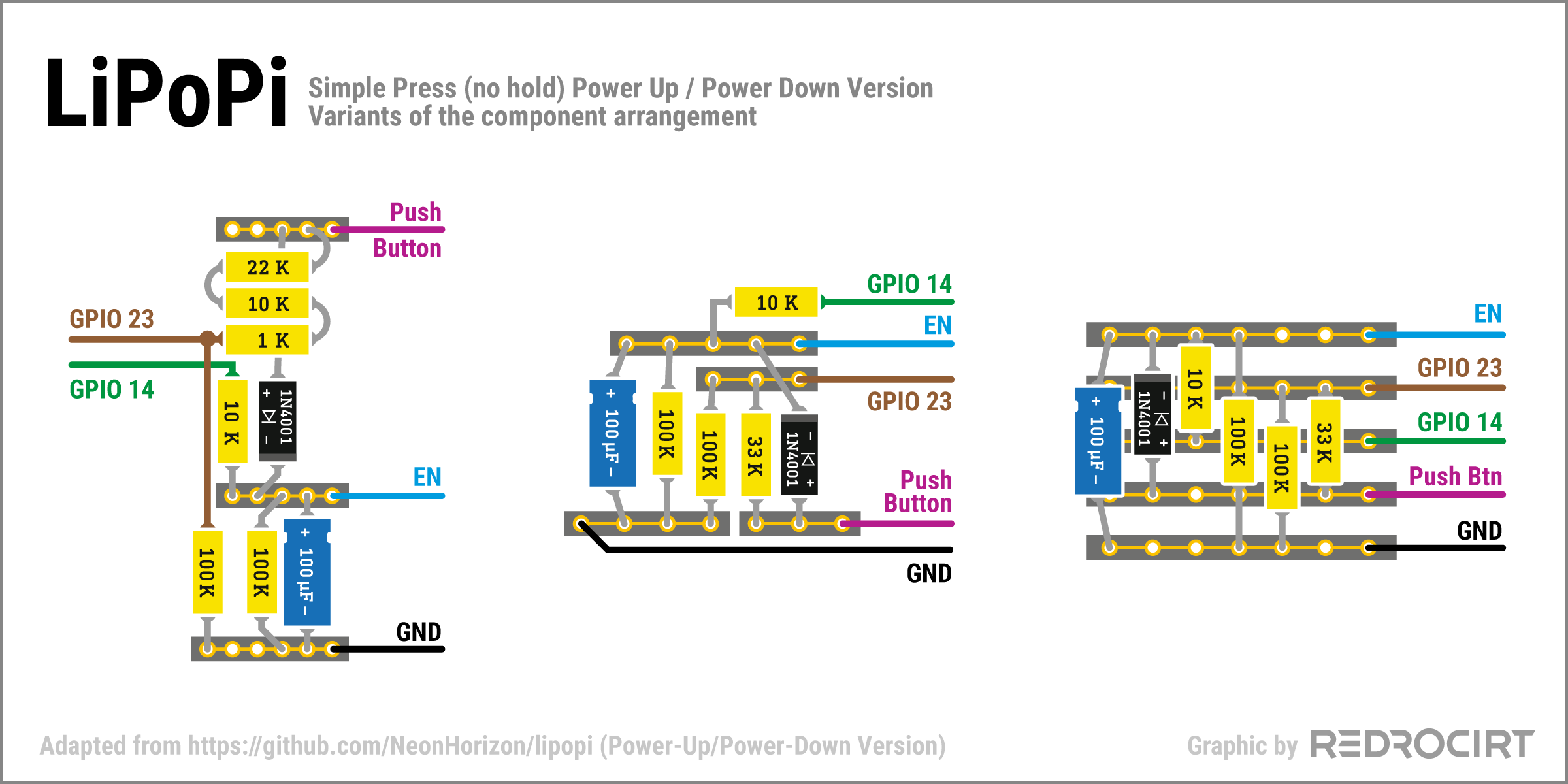
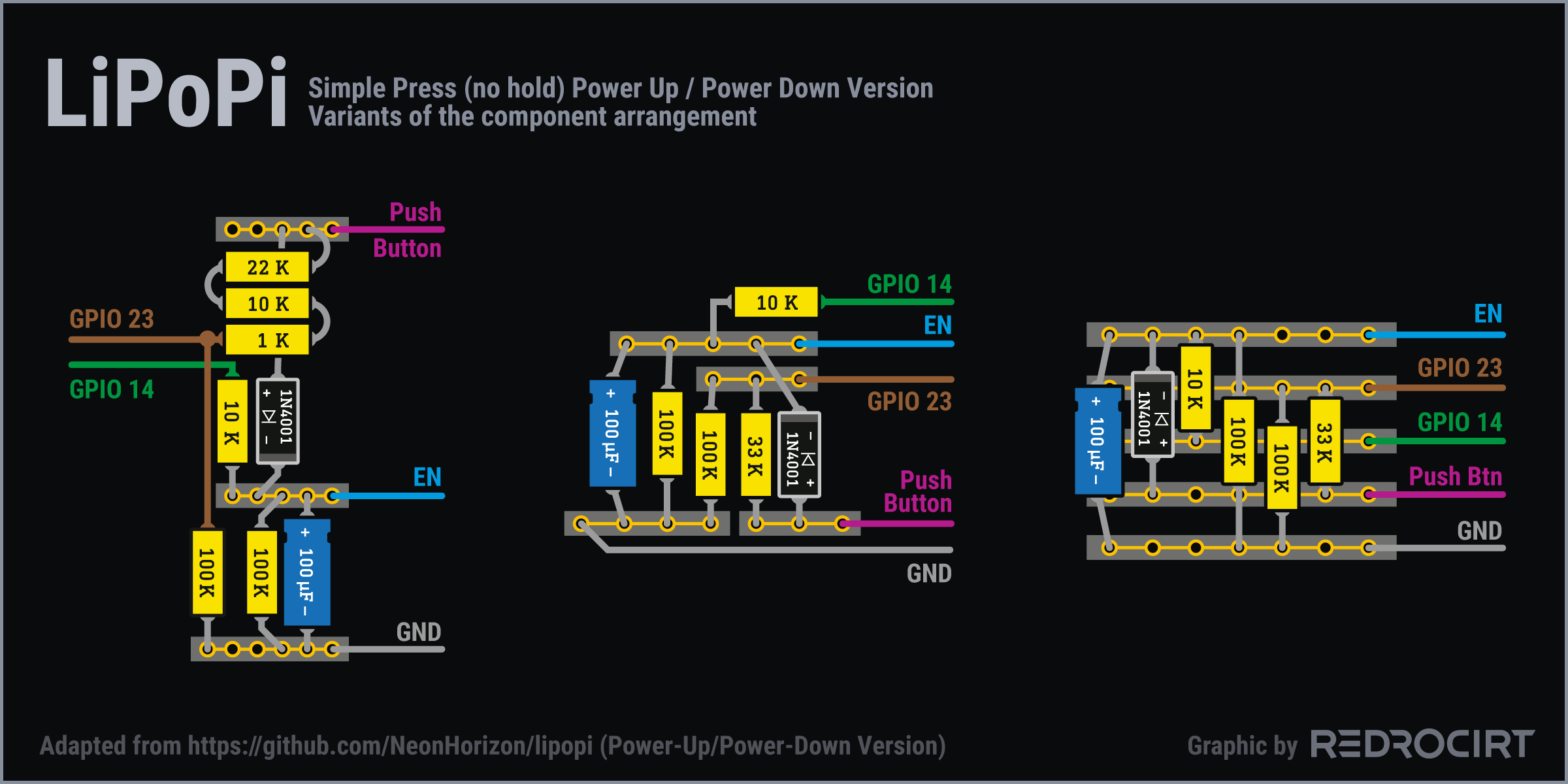
I forgot to take photos before adding the electrical insulation tape. The graphic below shows the component arrangement of my first improvised circuit (left version), as well as later variants (middle and right version). The black bars with gold contacts symbolize parts of a strip grid board.
Script adjustments
Section titled Script adjustmentsBefore I connected the test circuit to the Raspi, I prepared the files on the Raspberry Pi. First I created the folder /home/pi/lipopi/ and copied the files lipopi.py and lipopi.service from GitHub to this folder. Then I made small adjustments to the Python script lipopi.py.
I had to change the GPIO number for the shutdown pin:
# Specify which GPIO pins to use
lipopi['low_battery_pin'] = 15
# CHANGED: use GPIO 23 instead of 18 for shutdown:
lipopi['shutdown_pin'] = 23
I created a sub folder /home/pi/lipopi/log/ with an empty file lipopi.log and changed the path in the script accordingly:
# Full path to the log file
# CHANGED: Directory for the log file:
lipopi['logfile'] = '/home/pi/lipopi/log/lipopi.log'
Script and Service installation
Section titled Script and Service installationLiPoPi installation instructions on GitHub
Before connecting the test circuit to the Raspi, you have to disable the serial output at GPIO 14. This is done with raspi-config.
- Started LXTerminal (console) and then entered:
sudo raspi-config- Used arrow keys to go to 3 Interfacing Options, confirmed with ENTER key
- Used arrow keys to go to P6 Serial Port, confirmed with ENTER key
- Question "Would you like a login shell to be accessible over serial?": Selected NO, confirmed with ENTER key. This should disable console output on the serial interface.
- Question "Would you like the serial port hardware to be enabled?": Selected YES, confirmed with ENTER key
- Confirmed changes once again with OK
- Back in the settings overview: Used tabulator key to jump to the bottom menu, selected FINISH and confirmed with ENTER key
- Question "Would you like to reboot now?": Selected YES, confirmed with ENTER key
- Reboot
Now I changed the file permissions in the lipopifolder:
- Started File Manager
- Selected folder /home/pi/lipopi/
- Right clicked on file lipopi.py and selected file properties in the context menu
- Tab Permissions: Selected Everybody at Change content and Execute
- Confirmed with OK
Next I installed the lipopi.service as described on GitHub:
- Started LXTerminal (console), changed to lipopi folder:
cd lipopi- Copied the lipopi "service" file in the system folder:
(Note: don't forget the dot at the end of the line)
sudo cp lipopi.service /etc/systemd/system/.- Enabled and started the service:
sudo systemctl enable lipopi.service
sudo systemctl start lipopi.service- Raspi was shutting down as expected, as there was no PowerBoost/LiPoPi signal yet
Testing and revision
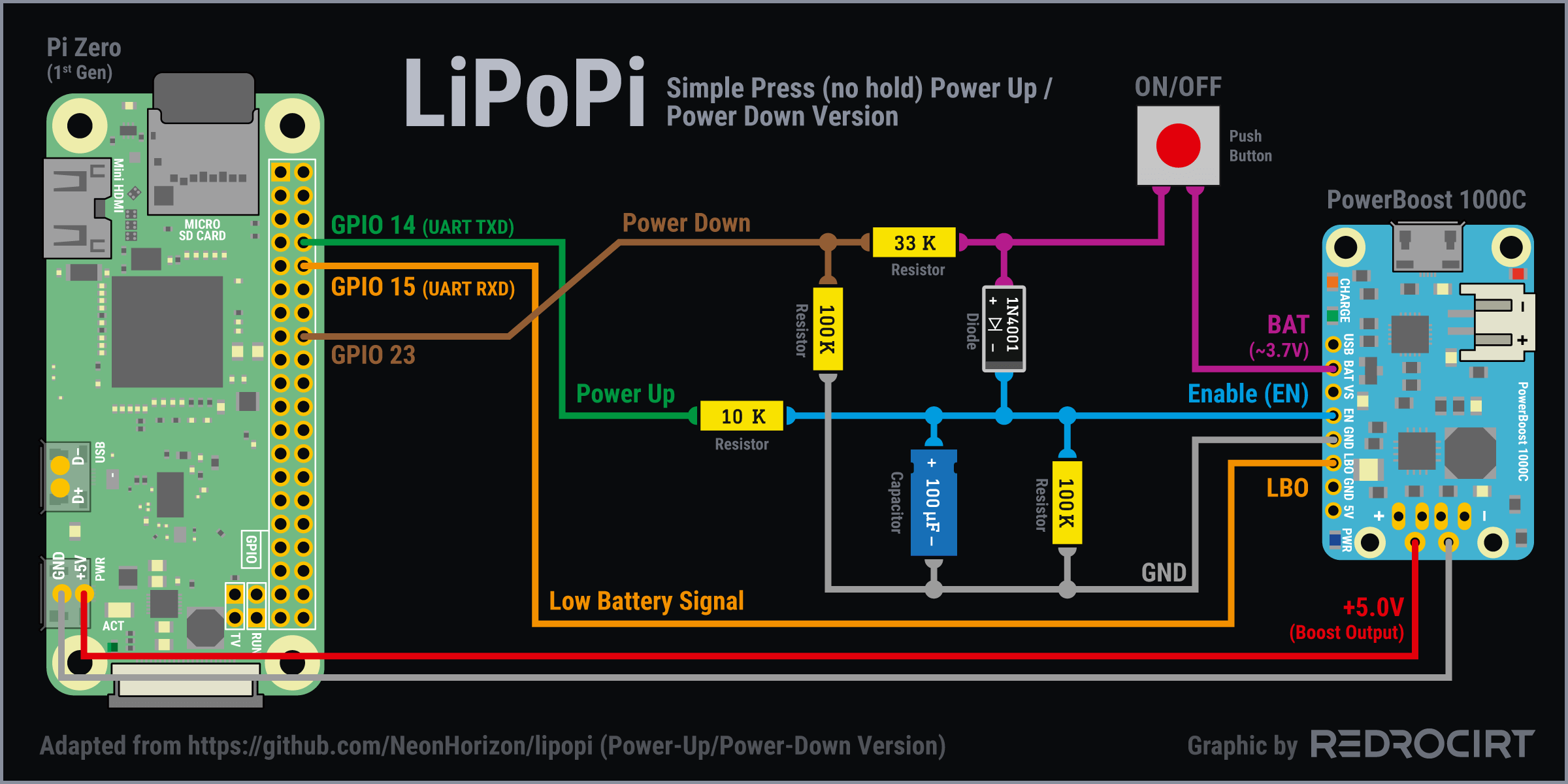
Section titled Testing and revisionFinally, I connected my LiPoPi test circuit the the Raspberry Pi and tested everything.
Of course, it didn't work on the first try. In the following days I soldered and tested the other variants of the test circuit, also to make it more compact than my first variant. I noticed that the capacitor gets very hot very quickly when soldering and I think I burned several of them.
I eventually added "female" connectors of breadboard jumper wires, to make the capacitor replaceable without soldering. This solution is still very compact and works very well.
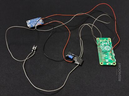
LiPoPi connected for testing 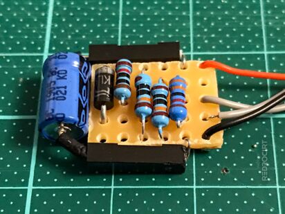
LiPoPi circuit version 4


Later added script adjustments
Section titled Later added script adjustmentsIn my later tests with connected LEDs the script triggered the shutdown quite often. I guess the blinking LEDs create current spikes and trigger the LBO (low battery) signal. Changing the bouncetime in the script lipopi.py seems to reduce the sensitivity for the shutdown signals.
# Create a trigger for the shutdown switch and low battery pins
# CHANGED: Bouncetime from 300 to 1000 (see end of lines):
GPIO.add_event_detect(lipopi['shutdown_pin'], GPIO.RISING, callback=lipopi_user_shutdown, bouncetime=1000)
GPIO.add_event_detect(lipopi['low_battery_pin'], GPIO.FALLING, callback=lipopi_low_battery_shutdown, bouncetime=1000)
I also changed the waiting time to shutdown without delay when the button is pressed.
# How log to wait before actual shutdown
# CHANGED: Set to 0 (no wait time):
lipopi['shutdown_wait'] = 0