Note: These were my first attempts. Later in the project, I dismissed the placements on the back lid.
Now that the hinges were done and my LiPoPi test circuit was ready, I turned my attention back to the arrangement of the modules on the back lid.
PowerBoost module next to Raspberry Pi Zero
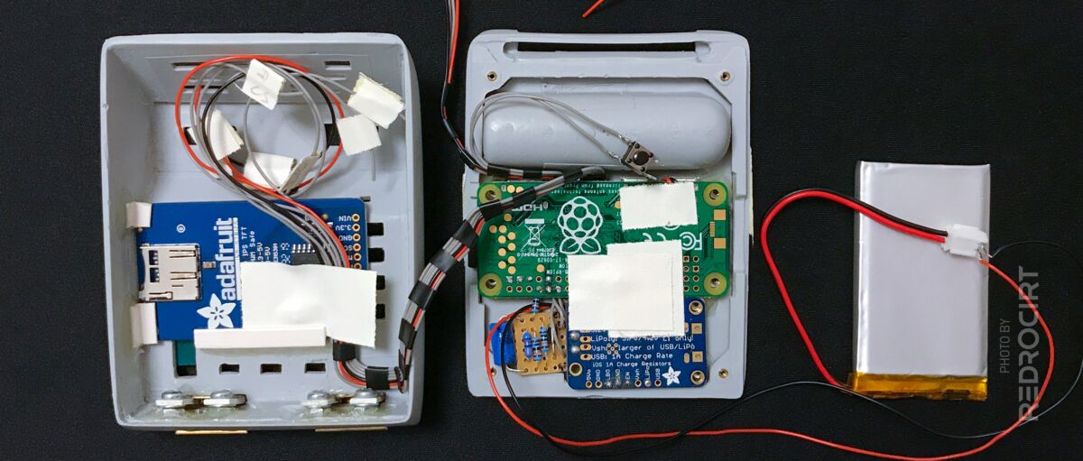
Section titled PowerBoost module next to Raspberry Pi ZeroThe PowerBoost module did fit next to the Raspberry Pi. The height of the JST battery connector was problematic because I wanted the module to be as flat as possible. I planned to remove the JST connector and place it elsewhere in the case, connected with wires to the PowerBoost module.
I wanted to mount the PowerBoost and Raspi upside down on the lid so that the electronic components are protected by the lid and to have a flat surface on top, since I wanted to put the battery on top of the modules. A more compact LiPoPi circuit would fit in the corner, next to the PowerBoost.

JST connector is too high 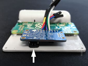
Should be flat without JST 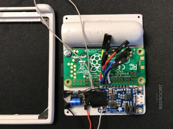
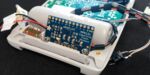
First LiPoPi circuit is to large


Adding nuts to fasten the boards to the lid
Section titled Adding nuts to fasten the boards to the lidI had ordered M2 screws and nuts to replace the M3 screws with the large heads. To do this, I first removed the M3 nuts and residue glue from the back lid.
To get the correct positions for gluing in the nuts, I placed screws in the mounting holes and secured them with one nut above and two nuts below the panel (the two below act as spacers). Then I glued them on the lid with a dot of strong epoxy and let it dry overnight.
The next day, I carefully unscrewed the screws and removed the board modules. Then I added the screws back in to make sure the two nuts were seated properly. Finally, I added more expoy around the nuts to make sure they wouldn't come loose, and again let the glue dry overnight.
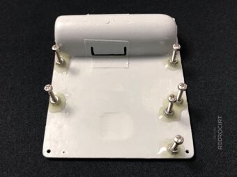
Glue new M2 nuts on the lid 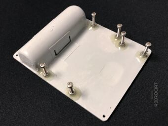
Temporary screws for alignment 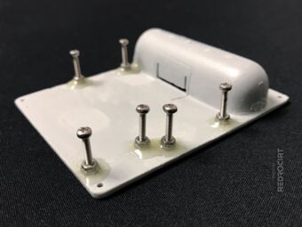
Bonding with ultra strong epoxy 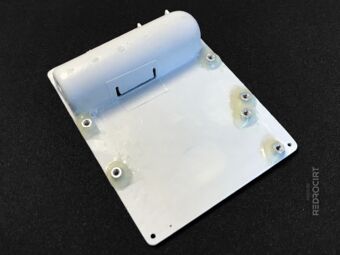
Some glue parts filed away... 
... for a better fitting 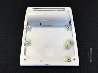
Back lid inserted into frame


Test wiring the TFT display
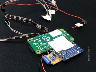
Section titled Test wiring the TFT displayMeanwhile I soldered flexible stranded wires to the TFT module and thought about the location of the wires in the shell. I thought it best to tape all the individual wires together so I would have a bundle of wires that I could easily bend and run along the walls of the enclosure.
(Hint: Later I replaced all the grey wires with colored wires to avoid confusion.)
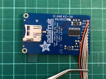
Wires aligned close together 
Fixed wires with insulating tape 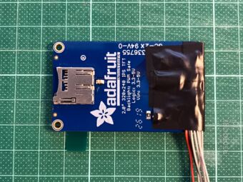
More tape to protect components 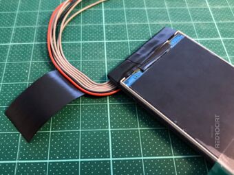
Bending and bundling wires 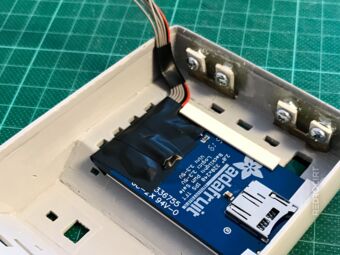
Test fitting and wire bending 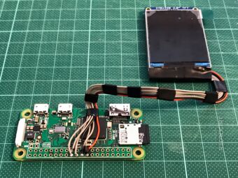
Test connection with bended wires


TFT display connected to SPI0
Section titled TFT display connected to SPI0I temporarily connected the TFT display to the Raspberry Pi as described in Adafruit's instructions.
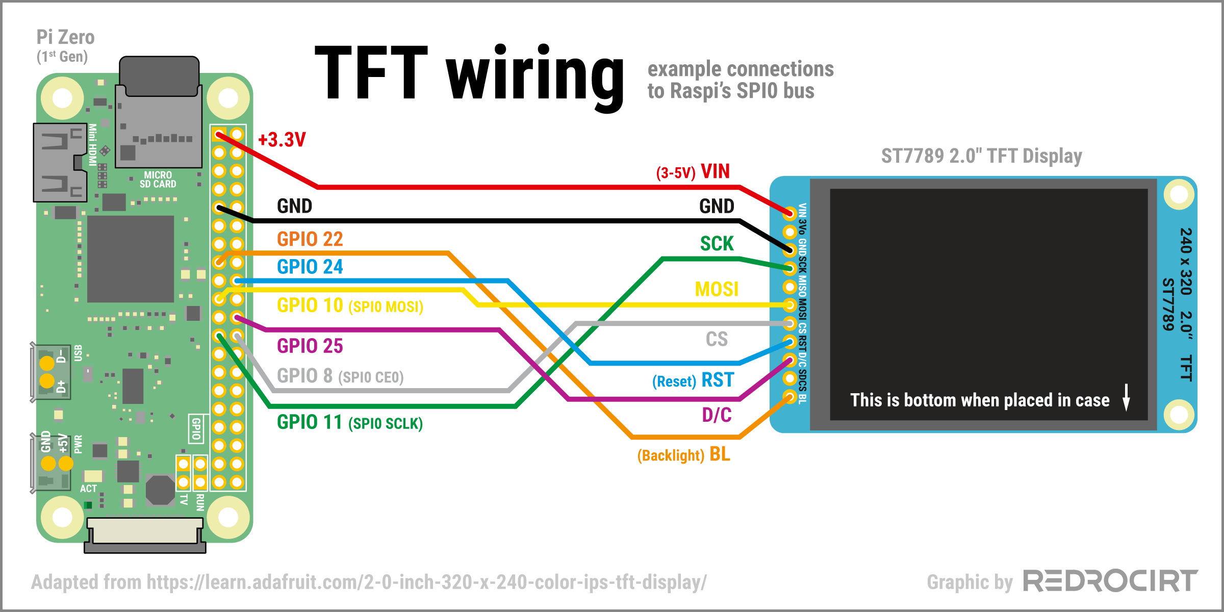
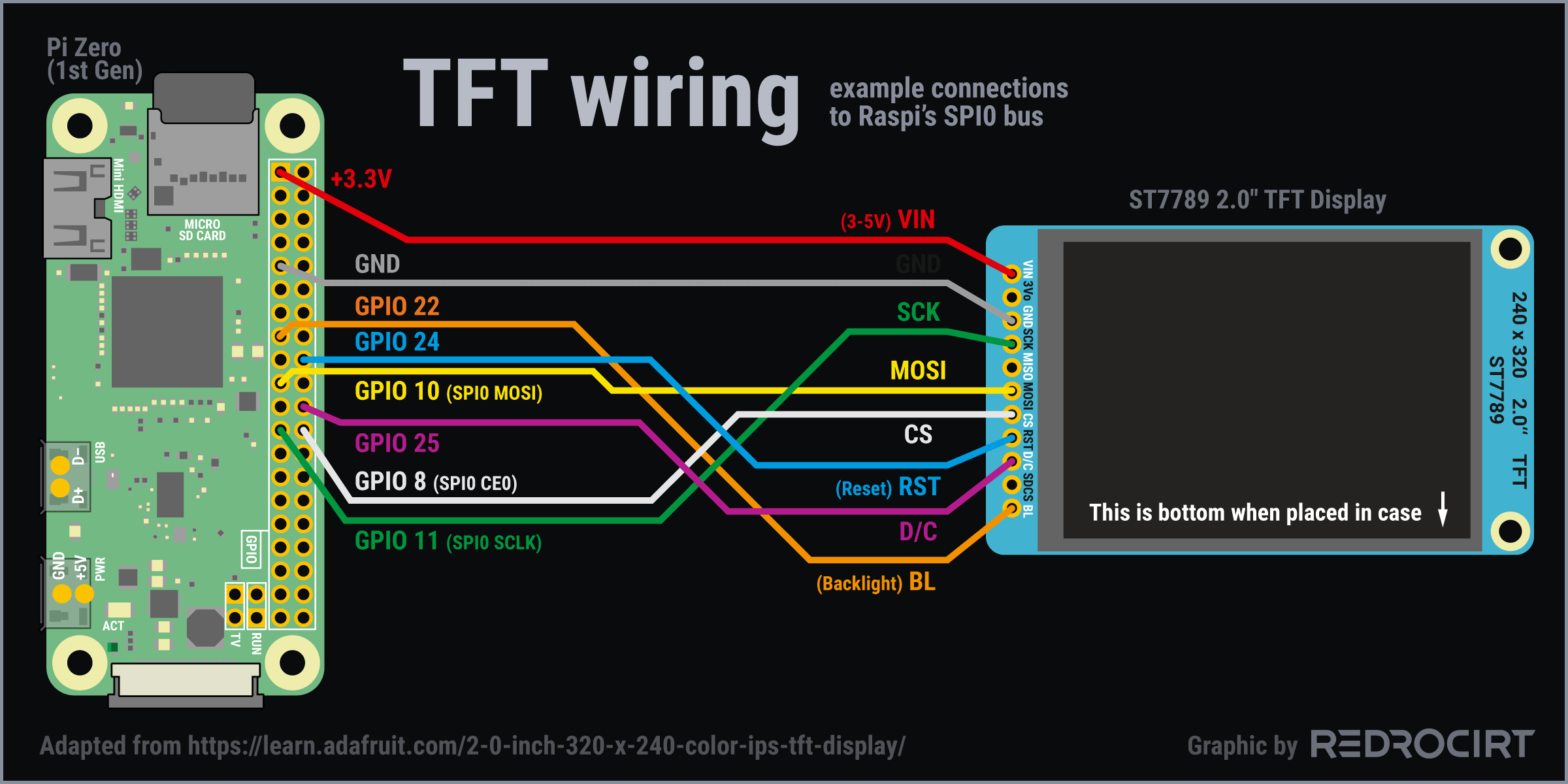
- The display's VIN power pin can handle 3-5V. I used Raspi's 3.3V GPIO for the test
- Connected GND (ground) pins
- Connected display's SCK (SPI clock input) pin to Raspi's GPIO 11 (SPI0 SCLK)
- Connected display's MOSI (SPI Microcontroller Out Serial In) to Raspi's GPIO 10 (SPIO0 MOSI)
- Connected display's CS (SPI chip select) pin to Raspi's GPIO 8 (SPIO0 CE0)
- Connected display's RST (reset pin) to Raspi's GPIO 24
- Connected display's D/C (SPI data or command selector) pin to Raspi's GPIO 25
- Connected display's BL (backlight) pin to Raspi's GPIO 22
Connect and place modules
Section titled Connect and place modulesI rebuilt the LiPoPi test circuit several times to find a compact version that would fit in the desired location. FInally I connected the modules and placed them in the shell. I had also redone the wiring for the TFT module several times to find a bend alignment and wire length I was happy with.
Second LiPoPi version in place 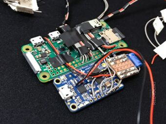
View of the components side 
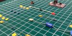
Test arrangement in the shell 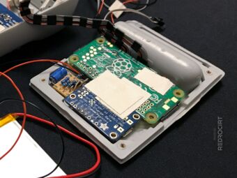
I filed a notch in the frame so that the PowerBoost fits better 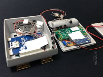
The TFT wires are long enough that you can still open the back lid 
The position for the power push button was still to be found