Disclaimer: I am not an expert in electronics or programming. That's the way I did it, and that's not necessarily the correct way to do it. Some driver information in this article may be out of date.
I was wondering if it is possible to connect a TLC5947 24-channel LED board in series with two DotStar 8×8 matrix boards (128 LEDs) and control them via Raspi's SPI1. Long story short: Yes, it is possible.
The LEDs on the 8×8 grid matrix boards are type APA102-2020 (datasheet), also known as “DotStar”. There are two ways to connect the boards: Via SPI or bit banged. According to the documentation, hardware SPI is “faster than bit-bang but you must use a hardware SPI interface and you cannot share the SPI device since there's no chip select”. This hint prompted me to test the bit banging method first, because I'm already using SPI0 for the TFT display and SPI1 for the TLC5947 LED board.
Testing the LED matrix with bit banging
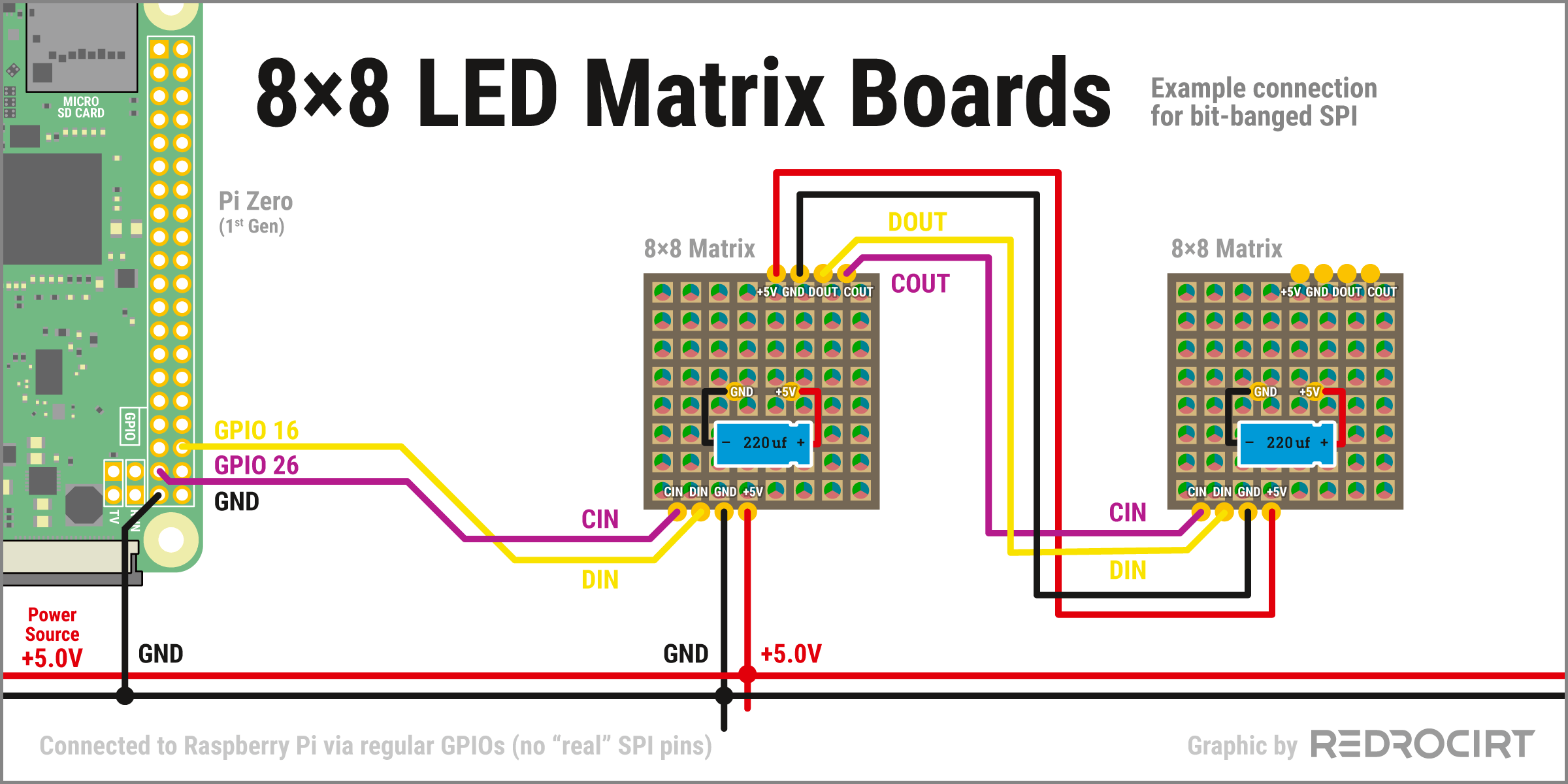
Section titled Testing the LED matrix with bit bangingThe setup is quite simple, you can use any available GPIO. I decided to use Raspi’s GPIO 16 for the connection to DIN (data-in) on the matrix and Raspi’s GPIO 26 for the connection to CIN (clock-in) on the matrix. The two matrix boards can be daisy chained by connecting the “out” pins of the first board with the “in” pins of the second board.
The matrix boards came with 220μF capacitors that should be soldered directly onto the back. Here's a simplified schematic of my first test setup:
Note: It is recommended to use a logic level shifter like 74AHCT125 to boost Raspi's 3.3V GPIO signals to 5V. I didn't use it, but I should have (it worked without, but not reliably). Use a logic level shifter!
Notes about power supply
Section titled Notes about power supplyEach of these RGB LEDs can consume up to 40 mAh at full brightness. For all 128 LEDs, that would be 5.12 Amps in the worst case. That is way too much to power the matrix boards via the +5.0V GPIO of the Raspberry Pi, it could burn the tiny traces. Therefore I connected the power pins directly to the +5.0V output of the PowerBoost module. That's probably still way too much for a battery powered system (the PowerBoost module has ~2.5A peak limiting), but I'm only going to use a fraction of the LEDs available and it is very unlikely that I will use them all together with full bright white.
The documentation says “three points are connected to ground: power supply, microcontroller and DotStar [matrix]. If there’s no common ground between the microcontroller and [the matrix], the LED’s won’t function properly”. I'm not sure if that means I should connect one of Raspi's GND GPIO to the common ground, since the Raspi is already connected to common ground through the main power supply. But an additional GND GPIO connection shouldn't be harmful, so I added it.
Installation and function test
Section titled Installation and function testTo use the CircuitPython DotStar Library on the RaspberryPi you have to install the adafruit_blinka library first. I already had Blinka installed when I tested the TLC5947 LED board, so I skipped this step. Last thing to do was running this in the command line:
sudo pip3 install adafruit-circuitpython-dotstarFor the first test I used the example from the documentation and only changed the initialization line:
# Using two 8x8 DotStar LED Matrix boards with 128 LEDs
# connected to digital pins: GPIO 16 for DIN and GPIO 26 for CIN
dots = dotstar.DotStar(board.D16, board.D26, 128, brightness=0.2)
Although I had reduced the brightness to 0.2 (range 0 to 1.0), the PCBs still get relatively hot. I hope there will be no overheating problems later when I integrate the matrix boards into the shell.
Determining the LED numbers
Section titled Determining the LED numbersSince only some of the LEDs will be visible later, I had to determine the numbering of the relevant LEDs.
# Excerpt from the Python test script
# [...]
dots.fill((0, 0, 0))
dots.show()
time.sleep(5)
dots[0] = (0, 255, 0)
dots.show()
print('Number 0 is green')
time.sleep(5)
dots[0] = (0, 0, 0)
dots[1] = (0, 255, 0)
dots.show()
print('Number 1 is green')
time.sleep(5)
dots[1] = (0, 0, 0)
dots[2] = (0, 255, 0)
dots.show()
print('Number 2 is green')
time.sleep(5)
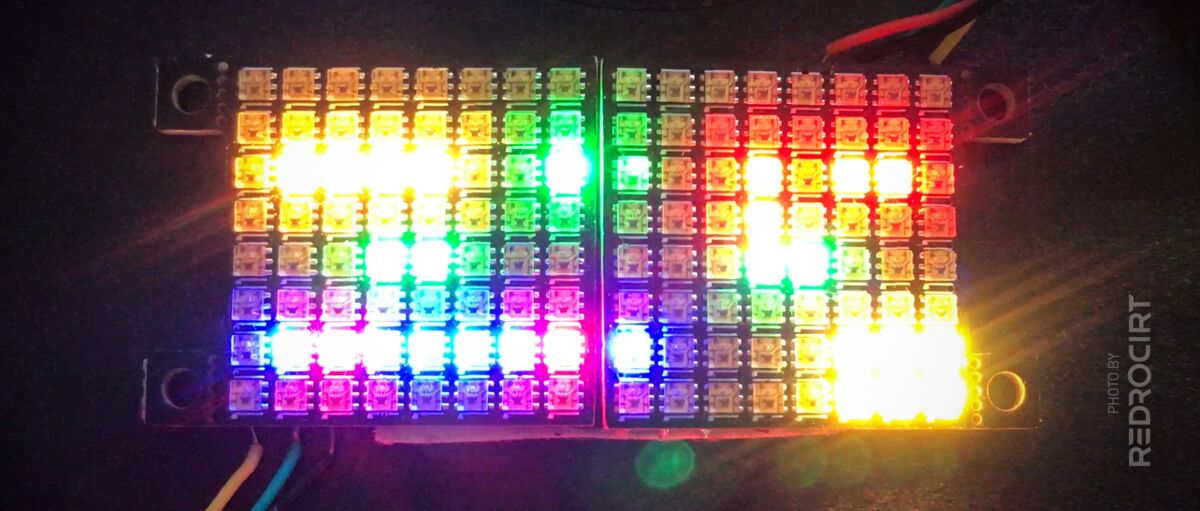
# [...]I made a drawing of the two matrix boards, added the LED numbering I determined from the test script, and outlined the LEDs I thought were relevant for the visible scanner front. I skipped the first two rows because they will be hidden inside the shell according to my fitting tests.
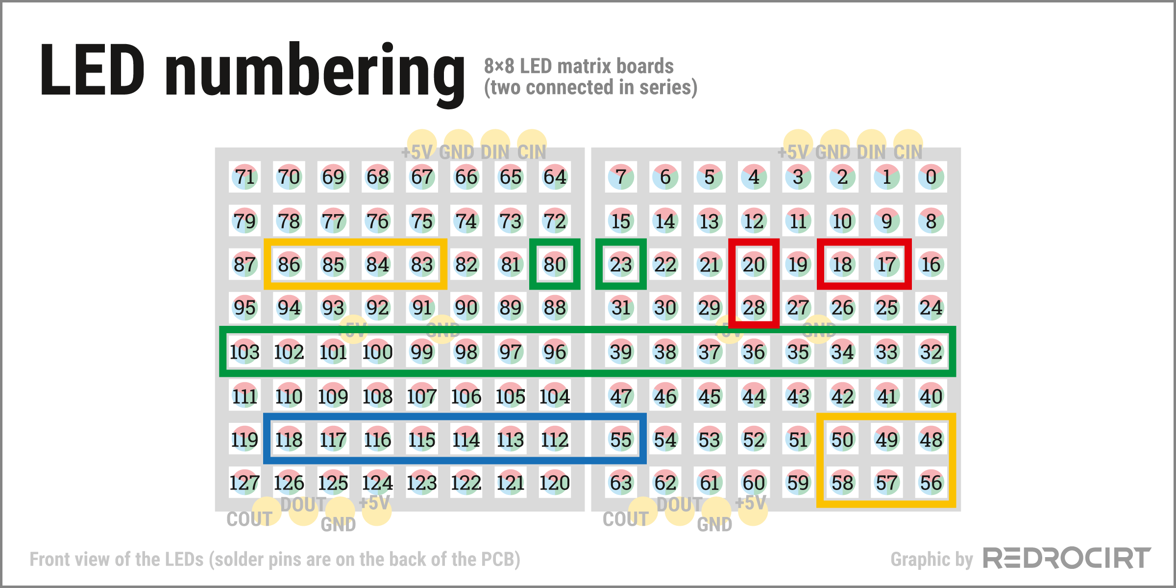
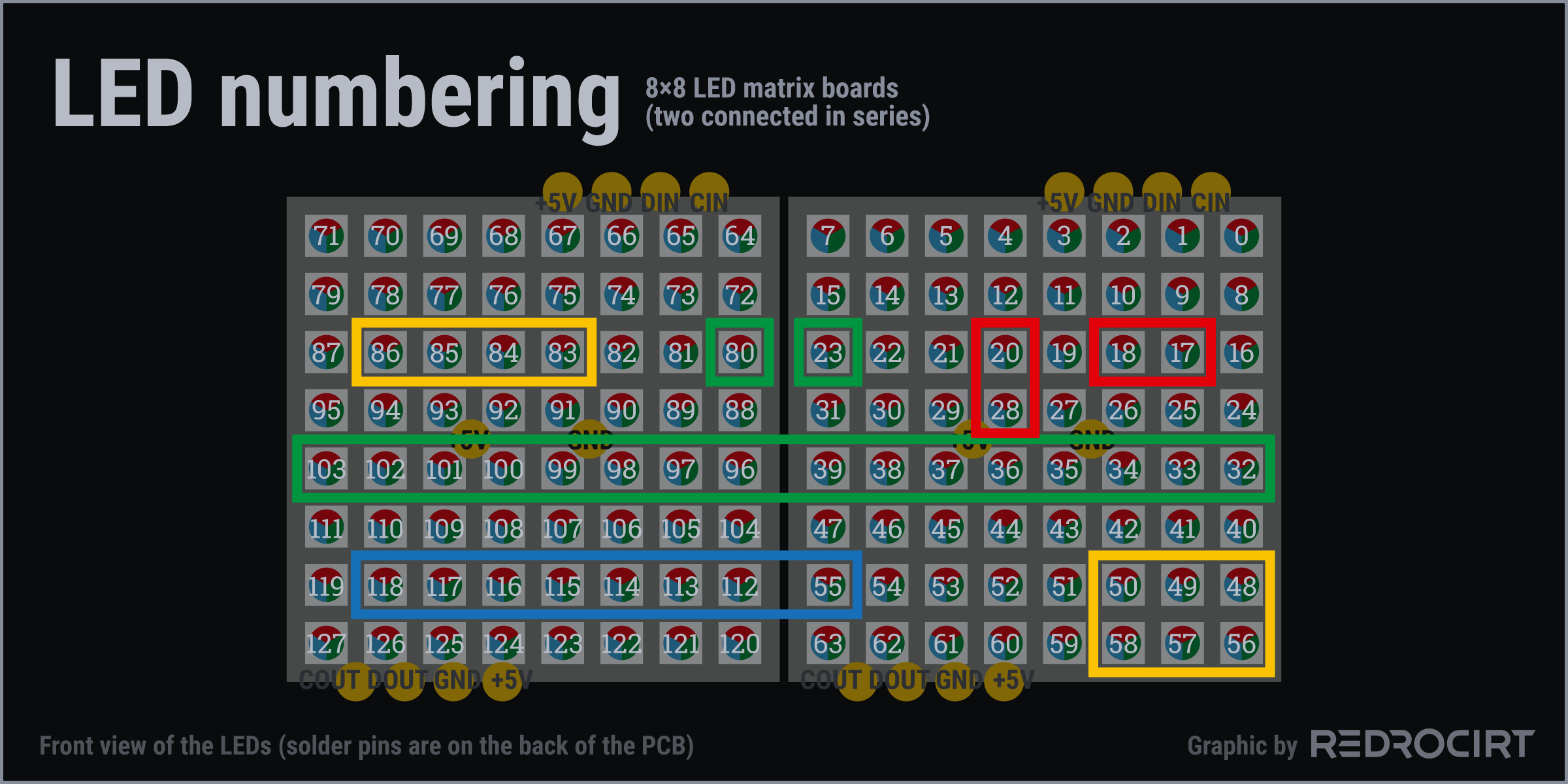
Note: I later rotated the matrix boards so that the solder pins were sideways in the shell, rather than on the top and bottom. This changed all the LED numbers and I had to adjust the Python scripts accordingly.
Test script with selected LEDs
Section titled Test script with selected LEDsTo get a more realistic use case, I changed my test script to light only the selected static LEDs in certain colors and to do some blinking tests in the while loop. I did not keep all the scripts from this tests, but they were basically similar to this version:
#!/usr/bin/python3
#!/usr/bin/env python3

# Import libraries
import time
import random
import board
import adafruit_dotstar as dotstar

# Dotstar Matrix with 128 LEDs
# First position (SCLK): CIN = GPIO 26
# Second position (MOSI): DIN = GPIO 16
dots = dotstar.DotStar(board.D26, board.D16, 128, brightness=0.2)

# Reset (all LEDs off)
def fn_dots_reset():
  dots.fill((0, 0, 0))
  dots.show()

# Startup: Initial LED settings
def fn_dots_initial():
  # Row top left: yellow
  dots[86] = (150, 110, 0)
  dots[85] = (150, 110, 0)
  dots[84] = (150, 110, 0)
  dots[83] = (150, 110, 0)
  # Bullets top right: red
  dots[20] = (150, 0, 0)
  dots[28] = (150, 0, 0)
  # Square top right: red
  dots[18] = (150, 0, 0)
  dots[17] = (150, 0, 0)
  # Row bottom left: blue red
  dots[118] = (0, 0, 150)
  dots[117] = (150, 0, 0)
  dots[116] = (0, 0, 150)
  dots[115] = (0, 0, 150)
  dots[114] = (0, 0, 150)
  dots[113] = (0, 0, 150)
  dots[112] = (150, 0, 0)
  dots[55] = (0, 0, 150)
  # Row bottom right: yellow
  dots[50] = (128, 128, 0)
  dots[49] = (128, 128, 0)
  dots[48] = (128, 128, 0)
  dots[58] = (128, 128, 0)
  dots[57] = (128, 128, 0)
  dots[56] = (128, 128, 0)
  dots.show()

# Execute functions on startup
fn_dots_reset()
time.sleep(1)
fn_dots_initial()
time.sleep(2)

# Then run the blinking loop (simplified test with only 4 LEDs)
try:
  while True:
    dots[39] = (0, 30, 0)
    dots[38] = (0, 0, 0)
    dots[96] = (0, 30, 0)
    dots[97] = (0, 0, 0)
    dots.show()
    time.sleep(0.5)
    dots[39] = (0, 0, 0)
    dots[38] = (0, 30, 0)
    dots[96] = (0, 0, 0)
    dots[97] = (0, 30, 0)
    dots.show()
    time.sleep(0.5)

except KeyboardInterrupt:
  fn_dots_reset()
The bit-banging method worked, but I noticed some delays in the blinking sequence, depending on the speed (when reducing time.sleep to make it blink faster). Also, I was curious if there might be a way to drive the dotstars with SPI after all.
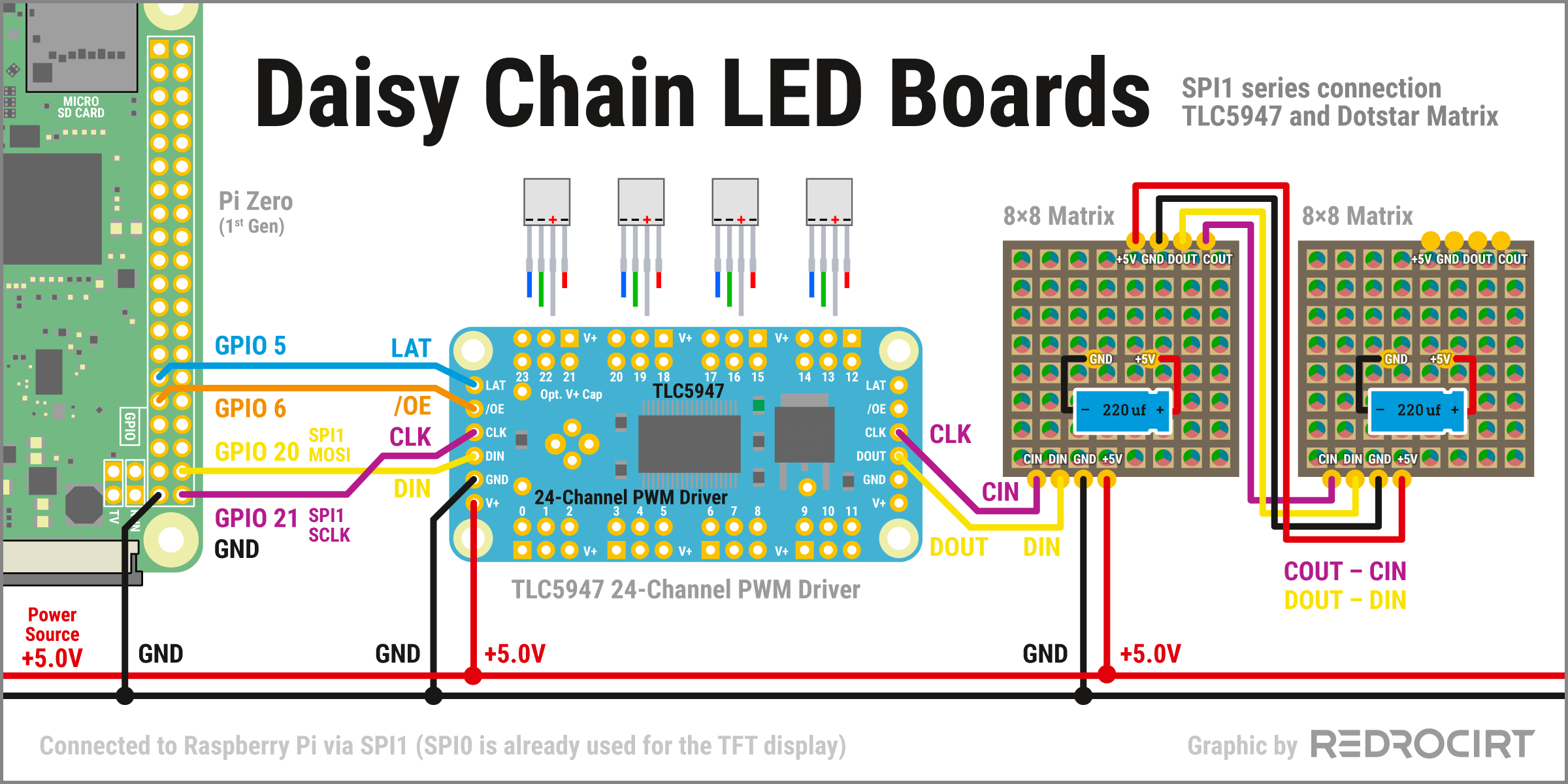
Daisy chain TLC5947 and DotStar Matrix via SPI1
Section titled Daisy chain TLC5947 and DotStar Matrix via SPI1As mentioned above, according to the DotStar Matrix documentation “you cannot share the SPI device since there's no chip select”. I thought maybe I don't need a chip select. Theoretically, both drivers (TLC5947 and Dotstar) are just simple shift registers:
The status for each LED is defined by 0 and 1, these commands are combined to a long string, sent over the data line to the connected boards and read by the LED microcontrollers when a signal is present on the clock line. To use the different LED boards on one SPI line you have to lengthen the shift register code, so append the control code for the DotStar LEDs to the control code for the TLC5947 LEDs.
Practically it is more complicated, because an LED can not only be 0 or 1, but each RGB channel can have a range value (e.g. 0-255) and also the brightness can be defined separately. And the control code for the DotStar LEDs is different to the TLC5947 LEDs. And “separator” bytearrays are required...
But anyway, before I took a closer look at the drivers, I first prepared the circuit. In my setup SPI0 is used for the TFT display and SPI1 is connected to the TLC5947 LED board. To daisy chain the LED boards I just connected DOUT (data-out) and CLK (clock-out) from the TLC5947 board with DIN (data-in) and CIN (clock-in) on the first Matrix board:
Note: It is recommended to use a logic level shifter like 74AHCT125 to boost Raspi's 3.3V GPIO signals to 5V. I didn't use it, but I should have (it worked without, but not reliably). Use a logic level shifter!
Adjustments in the existing driver
Section titled Adjustments in the existing driverAdafruit's open source drivers for the TLC5947 breakout and the Dotstar LEDs are available on GitHub. Each parameter and function is very well described in comments directly in the Python files.
- github.com/adafruit/Adafruit_CircuitPython_TLC5947 › adafruit_tlc5947.py
- github.com/adafruit/Adafruit_CircuitPython_DotStar › adafruit_dotstar.py
It took me a while to understand the various functions and how they interact with each other. After messing arround with the functions that create the shift registers, I finally chose a simpler approach:
- Comment out the SPI related code in the driver files of TLC5947 and Dotstar
- Return the shift register results instead of writing them directly to the SPI interface
- Add a new script that combines the two returned shift registers and write it to SPI
Modified TLC5947 driver file
Section titled Modified TLC5947 driver fileadafruit_
- Modified the __init__ function (commented out SPI stuff)
- Modified the write function (return shift_reg instead of writing to SPI)
Note: I worked on this in Sept/Oct. 2020. The current TLC5947 driver on GitHub may have changed.
# The MIT License (MIT)
#
# Copyright (c) 2017 Tony DiCola for Adafruit Industries
#
# Permission is hereby granted, free of charge, to any person obtaining a copy
# of this software and associated documentation files (the "Software"), to deal
# in the Software without restriction, including without limitation the rights
# to use, copy, modify, merge, publish, distribute, sublicense, and/or sell
# copies of the Software, and to permit persons to whom the Software is
# furnished to do so, subject to the following conditions:
#
# The above copyright notice and this permission notice shall be included in
# all copies or substantial portions of the Software.
#
# THE SOFTWARE IS PROVIDED "AS IS", WITHOUT WARRANTY OF ANY KIND, EXPRESS OR
# IMPLIED, INCLUDING BUT NOT LIMITED TO THE WARRANTIES OF MERCHANTABILITY,
# FITNESS FOR A PARTICULAR PURPOSE AND NONINFRINGEMENT. IN NO EVENT SHALL THE
# AUTHORS OR COPYRIGHT HOLDERS BE LIABLE FOR ANY CLAIM, DAMAGES OR OTHER
# LIABILITY, WHETHER IN AN ACTION OF CONTRACT, TORT OR OTHERWISE, ARISING FROM,
# OUT OF OR IN CONNECTION WITH THE SOFTWARE OR THE USE OR OTHER DEALINGS IN
# THE SOFTWARE.
"""
`adafruit_tlc5947`
====================================================

CircuitPython module for the TLC5947 12-bit 24 channel LED PWM driver.  See
examples/simpletest.py for a demo of the usage.

* Author(s): Tony DiCola, Walter Haschka

Implementation Notes
--------------------

**Hardware:**

* Adafruit `24-Channel 12-bit PWM LED Driver - SPI Interface - TLC5947
  <https://www.adafruit.com/product/1429>`_ (Product ID: 1429)

**Software and Dependencies:**

* Adafruit CircuitPython firmware for the ESP8622 and M0-based boards:
  https://github.com/adafruit/circuitpython/releases
"""
__version__ = "0.0.0-auto.0"
__repo__ = "https://github.com/adafruit/Adafruit_CircuitPython_TLC5947.git"

# Globally disable protected access.  Ppylint can't figure out the
# context for using internal decorate classes below.  In these cases protectected
# access is by design for the internal class.
# pylint: disable=protected-access

_CHANNELS = 24
_STOREBYTES = _CHANNELS + _CHANNELS // 2


class TLC5947:
    """TLC5947 12-bit 24 channel LED PWM driver.  Create an instance of this by
    passing in at least the following parameters:

    :param spi: The SPI bus connected to the chip (only the SCK and MOSI lines are
                used, there is no MISO/input).
    :param latch: A DigitalInOut instance connected to the chip's latch line.

    Optionally you can specify:

    :param auto_write: This is a boolean that defaults to True and will automatically
                       write out all the channel values to the chip as soon as a
                       single one is updated.  If you set to False to disable then
                       you MUST call write after every channel update or when you
                       deem necessary to update the chip state.

    :param num_drivers: This is an integer that defaults to 1. It stands for the
                        number of chained LED driver boards (DOUT of one board has
                        to be connected to DIN of the next). For each board added,
                        36 bytes of RAM memory will be taken. The channel numbers
                        on the driver directly connected to the controller are 0 to
                        23, and for each driver add 24 to the port number printed.
                        The more drivers are chained, the more viable it is to set
                        auto_write=False, and call write explicitly after updating
                        all the channels.
    """

    class PWMOut:
        """Internal PWMOut class that mimics the behavior of CircuitPython's
        PWMOut class but is associated with a channel on the TLC5947.  You can
        get and set the instance's duty_cycle property as a 16-bit PWM value
        (note there will be quantization errors as the TLC5947 is a 12-bit PWM
        chip, instead use the TLC5947 class item accessor notation for direct
        12-bit raw PWM channel access).  Note you cannot change the frequency
        as it is fixed by the TLC5947 to ~2.4-5.6 mhz.
        """

        def __init__(self, tlc5947, channel):
            self._tlc5947 = tlc5947
            self._channel = channel

        @property
        def duty_cycle(self):
            """Get and set the 16-bit PWM duty cycle value for this channel."""
            raw_value = self._tlc5947._get_gs_value(self._channel)
            # Convert to 16-bit value from 12-bits and return it.
            return (raw_value << 4) & 0xFFFF

        @duty_cycle.setter
        def duty_cycle(self, val):
            if val < 0 or val > 65535:
                raise ValueError(
                    "PWM intensity {0} outside supported range [0;65535]".format(val)
                )
            # Convert to 12-bit value (quantization error will occur!).
            val = (val >> 4) & 0xFFF
            self._tlc5947._set_gs_value(self._channel, val)

        @property
        def frequency(self):
            """Frequency of the PWM channel, note you cannot change this and
            cannot read its exact value (it varies from 2.4-5.6 mhz, see the
            TLC5947 datasheet).
            """
            return 0

        # pylint bug misidentifies the following as a regular function instead
        # of the associated setter: https://github.com/PyCQA/pylint/issues/870
        # Must disable a few checks to make pylint happy (ugh).
        # pylint: disable=no-self-use,unused-argument
        @frequency.setter
        def frequency(self, val):
            raise RuntimeError("Cannot set TLC5947 PWM frequency!")

        # pylint: enable=no-self-use,unused-argument


###########
# MODIFIED: Commented out SPI related code from the INIT function
###########
    def __init__(
        self,
#        spi,
#        latch,
        *,
        auto_write=True,
        num_drivers=1
    ):

        if num_drivers < 1:
            raise ValueError(
                "Need at least one driver; {0} is not supported.".format(num_drivers)
            )
#        self._spi = spi
#        self._latch = latch
#        self._latch.switch_to_output(value=False)
        # This device is just a big 36*n byte long shift register.  There's no
        # fancy protocol or other commands to send, just write out all 288*n
        # bits every time the state is updated.
        self._n = num_drivers
        self._shift_reg = bytearray(_STOREBYTES * self._n)
        # Save auto_write state (i.e. push out shift register values on
        # any channel value change).
        self.auto_write = auto_write

###########
# MODIFIED: Return the shift register instead of writing it to the SPI interface
###########
    def write(self):
        """Write out the current channel PWM values to the chip.  This is only
        necessary to call if you disabled auto_write in the initializer,
        otherwise write is automatically called on any channel update.
        """
        # Return the shift register
        return self._shift_reg
#       # Write out the current state to the shift register.
#        try:
#           # Lock the SPI bus and configure it for the shift register.
#            while not self._spi.try_lock():
#                pass
#            self._spi.configure(baudrate=1000000, polarity=0, phase=0, bits=8)
#            # First ensure latch is low.
#            self._latch.value = False
#            # Write out the bits.
#            self._spi.write(self._shift_reg, start=0, end=_STOREBYTES * self._n + 1)
#            # Then toggle latch high and low to set the value.
#            self._latch.value = True
#            self._latch.value = False
#        finally:
#            # Ensure the SPI bus is unlocked.
#            self._spi.unlock()

    def _get_gs_value(self, channel):
        # pylint: disable=no-else-return
        # Disable should be removed when refactor can be tested
        if channel < 0 or channel >= _CHANNELS * self._n:
            raise ValueError(
                "Channel {0} not available with {1} board(s).".format(channel, self._n)
            )
        # Invert channel position as the last channel needs to be written first.
        # I.e. is in the first position of the shift registr.
        channel = _CHANNELS * self._n - 1 - channel
        # Calculate exact bit position within the shift register.
        bit_offset = channel * 12
        # Now calculate the byte that this position falls within and any offset
        # from the left inside that byte.
        byte_start = bit_offset // 8
        start_offset = bit_offset % 8
        # Grab the high and low bytes.
        high_byte = self._shift_reg[byte_start]
        low_byte = self._shift_reg[byte_start + 1]
        if start_offset == 4:
            # Value starts in the lower 4 bits of the high bit so you can
            # just concat high with low byte and return the 12-bit value.
            return ((high_byte << 8) | low_byte) & 0xFFF
        elif start_offset == 0:
            # Value starts in the entire high byte and spills into upper
            # 4 bits of low byte.  Shift low byte and concat values.
            return ((high_byte << 4) | (low_byte >> 4)) & 0xFFF
        else:
            raise RuntimeError("Unsupported bit offset!")

    def _set_gs_value(self, channel, val):
        if channel < 0 or channel >= _CHANNELS * self._n:
            raise ValueError(
                "Channel {0} not available with {1} board(s).".format(channel, self._n)
            )
        if val < 0 or val > 4095:
            raise ValueError(
                "PWM intensity {0} outside supported range [0;4095]".format(val)
            )

        # Invert channel position as the last channel needs to be written first.
        # I.e. is in the first position of the shift registr.
        channel = _CHANNELS * self._n - 1 - channel
        # Calculate exact bit position within the shift register.
        bit_offset = channel * 12
        # Now calculate the byte that this position falls within and any offset
        # from the left inside that byte.
        byte_start = bit_offset // 8
        start_offset = bit_offset % 8
        # Grab the high and low bytes.
        high_byte = self._shift_reg[byte_start]
        low_byte = self._shift_reg[byte_start + 1]
        if start_offset == 4:
            # Value starts in the lower 4 bits of the high bit.
            high_byte &= 0b11110000
            high_byte |= val >> 8
            low_byte = val & 0xFF
        elif start_offset == 0:
            # Value starts in the entire high byte and spills into upper
            # 4 bits of low byte.
            high_byte = (val >> 4) & 0xFF
            low_byte &= 0b00001111
            low_byte |= (val << 4) & 0xFF
        else:
            raise RuntimeError("Unsupported bit offset!")
        self._shift_reg[byte_start] = high_byte
        self._shift_reg[byte_start + 1] = low_byte
        # Write the updated shift register values if required.
        if self.auto_write:
            self.write()

    def create_pwm_out(self, channel):
        """Create an instance of a PWMOut-like class that mimics the built-in
        CircuitPython PWMOut class but is associated with the TLC5947 channel
        that is specified.  This PWMOut class has a duty_cycle property which
        you can read and write with a 16-bit value to control the channel.
        Note there will be quantization error as the chip only supports 12-bit
        PWM, if this is problematic use the item accessor approach to update
        the raw 12-bit channel values.
        """
        return self.PWMOut(self, channel)

    # Define index and length properties to set and get each channel's raw
    # 12-bit value (useful for changing channels without quantization error
    # like when using the PWMOut mock class).
    def __len__(self):
        """Retrieve the total number of PWM channels available."""
        return _CHANNELS * self._n  # number channels times number chips.

    def __getitem__(self, key):
        """Retrieve the 12-bit PWM value for the specified channel (0-max).
        max depends on the number of boards.
        """
        if key < 0:  # allow reverse adressing with negative index
            key = key + _CHANNELS * self._n
        return self._get_gs_value(key)  # does parameter checking

    def __setitem__(self, key, val):
        """Set the 12-bit PWM value (0-4095) for the specified channel (0-max).
        max depends on the number of boards.
        If auto_write is enabled (the default) then the chip PWM state will
        immediately be updated too, otherwise you must call write to update
        the chip with the new PWM state.
        """
        if key < 0:  # allow reverse adressing with negative index
            key = key + _CHANNELS * self._n
        self._set_gs_value(key, val)  # does parameter checking
Modified DotStar driver file
Section titled Modified DotStar driver fileadafruit_
- Modified the __init__ and deinit functions (commented out SPI stuff)
- Modified the _transmit function (return buffer instead of writing to SPI)
Note: I worked on this in Sept/Oct. 2020. The current DotStar driver on GitHub may have changed.
# The MIT License (MIT)
#
# Copyright (c) 2016 Damien P. George (original Neopixel object)
# Copyright (c) 2017 Ladyada
# Copyright (c) 2017 Scott Shawcroft for Adafruit Industries
# Copyright (c) 2019 Roy Hooper
#
# Permission is hereby granted, free of charge, to any person obtaining a copy
# of this software and associated documentation files (the "Software"), to deal
# in the Software without restriction, including without limitation the rights
# to use, copy, modify, merge, publish, distribute, sublicense, and/or sell
# copies of the Software, and to permit persons to whom the Software is
# furnished to do so, subject to the following conditions:
#
# The above copyright notice and this permission notice shall be included in
# all copies or substantial portions of the Software.
#
# THE SOFTWARE IS PROVIDED "AS IS", WITHOUT WARRANTY OF ANY KIND, EXPRESS OR
# IMPLIED, INCLUDING BUT NOT LIMITED TO THE WARRANTIES OF MERCHANTABILITY,
# FITNESS FOR A PARTICULAR PURPOSE AND NONINFRINGEMENT. IN NO EVENT SHALL THE
# AUTHORS OR COPYRIGHT HOLDERS BE LIABLE FOR ANY CLAIM, DAMAGES OR OTHER
# LIABILITY, WHETHER IN AN ACTION OF CONTRACT, TORT OR OTHERWISE, ARISING FROM,
# OUT OF OR IN CONNECTION WITH THE SOFTWARE OR THE USE OR OTHER DEALINGS IN
# THE SOFTWARE.

"""
`adafruit_dotstar` - DotStar strip driver (for CircuitPython 5.0+ with _pixelbuf)
=================================================================================

* Author(s): Damien P. George, Limor Fried, Scott Shawcroft & Roy Hooper
"""

# pylint: disable=ungrouped-imports
import sys
import busio
import digitalio

if sys.implementation.version[0] < 5:
    import adafruit_pypixelbuf as _pixelbuf
else:
    try:
        import _pixelbuf
    except ImportError:
        import adafruit_pypixelbuf as _pixelbuf

__version__ = "0.0.0-auto.0"
__repo__ = "https://github.com/adafruit/Adafruit_CircuitPython_DotStar.git"

START_HEADER_SIZE = 4

# Pixel color order constants
RBG = "PRBG"
"""Red Blue Green"""
RGB = "PRGB"
"""Red Green Blue"""
GRB = "PGRB"
"""Green Red Blue"""
GBR = "PGBR"
"""Green Blue Red"""
BRG = "PBRG"
"""Blue Red Green"""
BGR = "PBGR"
"""Blue Green Red"""


class DotStar(_pixelbuf.PixelBuf):
    """
    A sequence of dotstars.

    :param ~microcontroller.Pin clock: The pin to output dotstar clock on.
    :param ~microcontroller.Pin data: The pin to output dotstar data on.
    :param int n: The number of dotstars in the chain
    :param float brightness: Brightness of the pixels between 0.0 and 1.0
    :param bool auto_write: True if the dotstars should immediately change when
        set. If False, `show` must be called explicitly.
    :param str pixel_order: Set the pixel order on the strip - different
         strips implement this differently. If you send red, and it looks blue
         or green on the strip, modify this! It should be one of the values above.
    :param int baudrate: Desired clock rate if using hardware SPI (ignored if
        using 'soft' SPI). This is only a recommendation; the actual clock
        rate may be slightly different depending on what the system hardware
        can provide.

    Example for Gemma M0:

    .. code-block:: python

        import adafruit_dotstar
        import time
        from board import *

        RED = 0x100000

        with adafruit_dotstar.DotStar(APA102_SCK, APA102_MOSI, 1) as pixels:
            pixels[0] = RED
            time.sleep(2)

    .. py:method:: DotStar.show()

        Shows the new colors on the dotstars themselves if they haven't already
        been autowritten.

        The colors may or may not be showing after this function returns because
        it may be done asynchronously.

    .. py:method:: DotStar.fill(color)

        Colors all dotstars the given ***color***.

    .. py:attribute:: brightness

        Overall brightness of all dotstars (0 to 1.0)
    """

###########
# MODIFIED: Commented out SPI related code from the INIT function
###########
    def __init__(
        self,
#        clock,
#        data,
        n,
        *,
        brightness=1.0,
        auto_write=True,
        pixel_order=BGR,
#        baudrate=4000000
    ):
#        self._spi = None
#        try:
#            self._spi = busio.SPI(clock, MOSI=data)
#            while not self._spi.try_lock():
#                pass
#            self._spi.configure(baudrate=baudrate)
#
#        except (NotImplementedError, ValueError):
#            self.dpin = digitalio.DigitalInOut(data)
#            self.cpin = digitalio.DigitalInOut(clock)
#            self.dpin.direction = digitalio.Direction.OUTPUT
#            self.cpin.direction = digitalio.Direction.OUTPUT
#            self.cpin.value = False

        # Supply one extra clock cycle for each two pixels in the strip.
        trailer_size = n // 16
        if n % 16 != 0:
            trailer_size += 1

        # Four empty bytes for the header.
        header = bytearray(START_HEADER_SIZE)
        # 0xff bytes for the trailer.
        trailer = bytearray(b"\xff") * trailer_size

        super().__init__(
            n,
            byteorder=pixel_order,
            brightness=brightness,
            auto_write=auto_write,
            header=header,
            trailer=trailer,
        )

###########
# MODIFIED: Commented out SPI related code from the DEINIT function
###########
    def deinit(self):
        """Blank out the DotStars and release the resources."""
        self.fill(0)
        self.show()
#        if self._spi:
#            self._spi.deinit()
#        else:
#            self.dpin.deinit()
#            self.cpin.deinit()

    def __enter__(self):
        return self

    def __exit__(self, exception_type, exception_value, traceback):
        self.deinit()

    def __repr__(self):
        return "[" + ", ".join([str(x) for x in self]) + "]"

    @property
    def n(self):
        """
        The number of dotstars in the chain (read-only)
        """
        return len(self)

###########
# MODIFIED: Return the buffer (shift register) instead of writing it to the SPI interface
###########
    def _transmit(self, buffer):
        return buffer
#        if self._spi:
#            self._spi.write(buffer)
#        else:
#            self._ds_writebytes(buffer)

#    def _ds_writebytes(self, buffer):
#        for b in buffer:
#            for _ in range(8):
#                self.dpin.value = b & 0x80
#                self.cpin.value = True
#                self.cpin.value = False
#                b = b << 1
#        self.cpin.value = False
New driver file to combine shift registers and write to SPI
Section titled New driver file to combine shift registers and write to SPIchain_
- The __init__ function declares the SPI and latch variables (latch is required by TLC5947 to set a value)
- The write function combines the two shift registers from TLC5947 and DotStar, writes the bits out via SPI and toggles latch for TLC5947
A quick note about the SPI baudrate: I used baudrate=1000000 as declared in the original TLC5947 driver because there is a comment that you can't change the frequency for TLC5947. According to the documentation, the DotStar LEDs are more flexible and can handle different speeds. So using baudrate=1000000 should not be a problem for the DotStar matrix boards.
import busio
import time

class chain_tlc5947_dotstar:

    def __init__(self, sck, mosi, latch):
        self._spi = busio.SPI(clock=sck, MOSI=mosi)
        self._latch = latch
        self._latch.switch_to_output(value=False)

    def write(self, shiftref_tlc5947, shiftref_dotstar):
        # Write out the current state to the shift register.
        try:
            # Lock the SPI bus and configure it for the shift register.
            while not self._spi.try_lock():
                pass
            self._spi.configure(baudrate=1000000)

            # First ensure latch is low.
            self._latch.value = False

            # Create combined shift register
            var_shiftreg_complete = shiftref_dotstar + shiftref_tlc5947

#            print('New SPI shift register:')
#            print(var_shiftreg_complete)

            # Write out the bits via SPI
            self._spi.write(var_shiftreg_complete)

            # Then toggle latch high and low to set the value on TLC5947
            self._latch.value = True
            self._latch.value = False

        finally:
            # Ensure the SPI bus is unlocked.
            self._spi.unlock()
Using the modified driver files
Section titled Using the modified driver filesTo use the modified drivers in your Python script, all the files should be placed in the same folder on the Pi (maybe there is a way to declare paths to the files, but I didn't care about that). In the “main” LED script (containing the LED color/power values and animation loops) you have to
- Import the modified TLC5947 driver
- Import the modified DotStar driver
- Import the new "chain" driver and declare the used SPI and latch channels
Note: I used auto_write=False in the initializations of TLC5947 and DotStar to avoid timing conflicts between the two drivers. The call to create or update the combined shift register is done separately.
# Import and initialize the custom driver for the TLC5947 24-channel LED board
import adafruit_tlc5947_custom
tlc5947 = adafruit_tlc5947_custom.TLC5947(auto_write=False)

# Import and initialize the custom driver for the Dotstar LEDs
# (I'm using two 8x8 matrix boards = 128 dots)
import adafruit_dotstar_custom
dots = adafruit_dotstar_custom.DotStar(128, brightness=0.2, auto_write=False)

# Import custom SPI driver for chained TCL5947 and Dotstar
import chain_write_tlc5947_dotstar
# Define GPIOs connected to the TLC5947 board
# I'm using the second SPI (= SPI1), because SPI0 is used for the TFT display
var_gpio_sck = board.SCK_1 # Second SLCK channel (GPIO 21 connected to TLC5947 SKL)
var_gpio_mosi = board.MOSI_1 # Second MOSI channel (GPIO 20 connected to TLC5947 DIN)
var_gpio_latch = digitalio.DigitalInOut(board.D5) # GPIO 5 for TLC5947 LAT control
# Initialize
ledchain = chain_write_tlc5947_dotstar.chain_tlc5947_dotstar(var_gpio_sck, var_gpio_mosi, var_gpio_latch)
Then you can write some functions to define LED colors or animations.
To write the shift register out via SPI you have to call the ledchain.write() function with tlc5947.write() and dots.show() as parameters. Simplified example:
# Turn on regular LED connected to TLC5947 channel 13 (range 0-4095)
tlc5947[13] = 4095
# Light DotStar No. 25 green (range 0-255):
dots[25] = (0, 255, 0)
# Apply changes: Write out SPI
ledchain.write(tlc5947.write(), dots.show())
Instead of manually calling the ledchain.write() function several times in multiple functions, I wrote a threading function fn_led_spi_update() with a while loop that updates the shift register every 0.01 seconds. This way you can use multiple threading functions for independent LED animations with different timings in while loops and the changes are all written to SPI automatically by this one function.
# Animation SPI write out loop
# Write every 0.01 sec
# This loop is to avoid multiple SPI calls at same time
def fn_led_spi_update(arg):
  t = threading.currentThread()
  while getattr(t, "do_run", True):
    # Apply changes: Write out SPI
    ledchain.write(tlc5947.write(), dots.show())
    time.sleep(0.01)
I created a separate file ledsequences.py that contains both the above codes and all the LED blinking sequences in separate threading functions. This way I could keep my main script (with the touch button logic) simpler.
# Abridged excerpt from ledsequences.py

# Import libraries
import board
import busio
import digitalio
import RPi.GPIO as GPIO # for reading/setting GPIO signals
import time # for timing control
import threading # for executing multiple functions parallel
import adafruit_tlc5947_custom # for 24 channel LED controll board

# Import and initialize the custom driver for the TLC5947 24-channel LED board
import adafruit_tlc5947_custom
tlc5947 = adafruit_tlc5947_custom.TLC5947(auto_write=False)

# Import and initialize the custom driver for the Dotstar LEDs
# (I'm using two 8x8 matrix boards = 128 dots)
import adafruit_dotstar_custom
dots = adafruit_dotstar_custom.DotStar(128, brightness=0.2, auto_write=False)

# Import custom SPI driver for chained TCL5947 and Dotstar
import chain_write_tlc5947_dotstar
# Define GPIOs connected to the TLC5947 board
# I'm using the second SPI (= SPI1), because SPI0 is used for the TFT display
var_gpio_sck = board.SCK_1 # Second SLCK channel (GPIO 21 connected to TLC5947 SKL)
var_gpio_mosi = board.MOSI_1 # Second MOSI channel (GPIO 20 connected to TLC5947 DIN)
var_gpio_latch = digitalio.DigitalInOut(board.D5) # GPIO 5 for TLC5947 LAT control
# Initialize
ledchain = chain_write_tlc5947_dotstar.chain_tlc5947_dotstar(var_gpio_sck, var_gpio_mosi, var_gpio_latch)

# To turn off all TCL5947 LEDs you can set the "/OE" (enabled) pin high
# OE connected to GPIO 6, signal high = LED off, signal low = LED on
var_gpio_ledoe = 6
GPIO.setmode(GPIO.BCM)
GPIO.setup(var_gpio_ledoe, GPIO.OUT)

# LED board power on
def fn_led_on():
  GPIO.output(var_gpio_ledoe, GPIO.LOW) # Low = LEDs on

# LED board power off
def fn_led_off():
  GPIO.output(var_gpio_ledoe, GPIO.HIGH) # High = LEDs off

# LED board power toggle
def fn_led_toggle():
  if GPIO.input(var_gpio_ledoe) == True:
    # GPIO True/1/HIGH = LEDs off: turn on (set LOW)
    fn_led_on()
  else:
    # GPIO False/0/LOW = LEDs on: turn off (set HIGH)
    fn_led_off()

# Reset (all LED off)
def fn_led_reset():
  ##### TLC5947 LED board #####
  # Note: If the first DotStar flickers try to set every 2nd TLC5947 LED
  # to 1 instead of 0 to avoid a bit row of too many zeros
  tlc5947[0] = 0
  tlc5947[1] = 0
  tlc5947[2] = 0
  tlc5947[3] = 0
  tlc5947[4] = 0
  tlc5947[5] = 0
  tlc5947[6] = 0
  tlc5947[7] = 0
  tlc5947[8] = 0
  tlc5947[9] = 0
  tlc5947[10] = 0
  tlc5947[11] = 0
  tlc5947[12] = 0
  tlc5947[13] = 0
  tlc5947[14] = 0
  tlc5947[15] = 0
  tlc5947[16] = 0
  tlc5947[17] = 0
  tlc5947[18] = 0
  tlc5947[19] = 0
  tlc5947[20] = 0
  tlc5947[21] = 0
  tlc5947[22] = 0
  tlc5947[23] = 0
  ##### DotStar Matrix Front #####
  # All off:
  dots.fill((0, 0, 0))
  ##### Apply changes: Write out SPI #####
  ledchain.write(tlc5947.write(), dots.show())

# Animation SPI write out loop
# Write every 0.01 sec
# This loop is to avoid multiple SPI calls at same time
def fn_led_spi_update(arg):
  t = threading.currentThread()
  while getattr(t, "do_run", True):
    # Apply changes: Write out SPI
    ledchain.write(tlc5947.write(), dots.show())
    time.sleep(0.01)

###############################
# Startup: Initial LED settings
###############################

##### TLC5947 LED board #####
def fn_led_initial(sleep):
  if sleep == True:
    tlc5947[13] = 0
    tlc5947[14] = 0
    tlc5947[18] = 0
    tlc5947[8] = 0
    tlc5947[7] = 0
  else:
    # Top red LEDs
    tlc5947[13] = 1024
    tlc5947[14] = 700
    tlc5947[18] = 700
    # Bottom EMRG
    tlc5947[8] = 1024
    # Bottom ID blue
    tlc5947[7] = 700

##### DotStar Matrix Front #####
def fn_led_front_initial(sleep, style):
  if sleep == True:
    dots[86] = (0, 0, 0)
    dots[85] = (0, 0, 0)
    dots[84] = (0, 0, 0)
    dots[83] = (0, 0, 0)
    dots[20] = (0, 0, 0)
    dots[28] = (0, 0, 0)
    dots[18] = (0, 0, 0)
    dots[17] = (0, 0, 0)
    dots[118] = (0, 0, 0)
    dots[117] = (0, 0, 0)
    dots[116] = (0, 0, 0)
    dots[115] = (0, 0, 0)
    dots[114] = (0, 0, 0)
    dots[113] = (0, 0, 0)
    dots[112] = (0, 0, 0)
    dots[55] = (0, 0, 0)
    dots[50] = (0, 0, 0)
    dots[49] = (0, 0, 0)
    dots[48] = (0, 0, 0)
    dots[58] = (0, 0, 0)
    dots[57] = (0, 0, 0)
    dots[56] = (0, 0, 0)
  else:
    # static colors for GEO modus
    if (style == "geo"):
      # Row top left: yellow
      dots[86] = (150, 100, 0)
      dots[85] = (150, 100, 0)
      dots[84] = (150, 100, 0)
      dots[83] = (150, 100, 0)
      # Bullets top right: red
      dots[20] = (150, 0, 0)
      dots[28] = (150, 0, 0)
      # Square top right: red
      dots[18] = (150, 0, 0)
      dots[17] = (150, 0, 0)
      # Row bottom left: green
      dots[118] = (0, 150, 0)
      dots[117] = (0, 150, 0)
      dots[116] = (0, 150, 0)
      dots[115] = (0, 150, 0)
      dots[114] = (0, 150, 0)
      dots[113] = (0, 150, 0)
      dots[112] = (0, 150, 0)
      dots[55] = (0, 150, 0)
      # Row bottom right: yellow
      dots[50] = (150, 110, 0)
      dots[49] = (150, 110, 0)
      dots[48] = (150, 110, 0)
      dots[58] = (150, 110, 0)
      dots[57] = (150, 110, 0)
      dots[56] = (150, 110, 0)
    # [... and other styles in elif() here ...]

###############################
# LED Alpha-Gamma
###############################

# off = all 0 (alpha beta gamma delta)
def fn_led_alphagamma_off():
  tlc5947[20] = 0
  tlc5947[21] = 0
  tlc5947[22] = 0
  tlc5947[23] = 0

# LED Alpha-Gamma
def fn_led_alphagamma(arg):
  t = threading.currentThread()
  while getattr(t, "do_run", True):
    if (getattr(t, "sleep") == True):
      fn_led_alphagamma_off()
      time.sleep(0.1)
    else:
      # direction down: alpha - beta - gamma - delta
      if (getattr(t, "style") == "down"):
        if (getattr(t, "sleep") == False):
          tlc5947[20] = 4095
          tlc5947[21] = 1
          tlc5947[22] = 1
          tlc5947[23] = 1
          time.sleep(0.25)
          if (getattr(t, "do_run") == False):
            fn_led_alphagamma_off()
            break
        if (getattr(t, "sleep") == False):
          tlc5947[20] = 1
          tlc5947[21] = 4095
          tlc5947[22] = 1
          tlc5947[23] = 1
          time.sleep(0.25)
          if (getattr(t, "do_run") == False):
            fn_led_alphagamma_off()
            break
        if (getattr(t, "sleep") == False):
          tlc5947[20] = 1
          tlc5947[21] = 1
          tlc5947[22] = 4095
          tlc5947[23] = 1
          time.sleep(0.25)
          if (getattr(t, "do_run") == False):
            fn_led_alphagamma_off()
            break
        if (getattr(t, "sleep") == False):
          tlc5947[20] = 1
          tlc5947[21] = 1
          tlc5947[22] = 1
          tlc5947[23] = 4095
          time.sleep(0.25)
          if (getattr(t, "do_run") == False):
            fn_led_alphagamma_off()
            break
      # direction up: delta - gamma - beta - alpha
      elif (getattr(t, "style") == "up"):
        if (getattr(t, "sleep") == False):
          tlc5947[20] = 1
          tlc5947[21] = 1
          tlc5947[22] = 1
          tlc5947[23] = 4095
          time.sleep(0.25)
          if (getattr(t, "do_run") == False):
            fn_led_alphagamma_off()
            break
        if (getattr(t, "sleep") == False):
          tlc5947[20] = 1
          tlc5947[21] = 1
          tlc5947[22] = 4095
          tlc5947[23] = 1
          time.sleep(0.25)
          if (getattr(t, "do_run") == False):
            fn_led_alphagamma_off()
            break
        if (getattr(t, "sleep") == False):
          tlc5947[20] = 1
          tlc5947[21] = 4095
          tlc5947[22] = 1
          tlc5947[23] = 1
          time.sleep(0.25)
          if (getattr(t, "do_run") == False):
            fn_led_alphagamma_off()
            break
        if (getattr(t, "sleep") == False):
          tlc5947[20] = 4095
          tlc5947[21] = 1
          tlc5947[22] = 1
          tlc5947[23] = 1
          time.sleep(0.25)
          if (getattr(t, "do_run") == False):
            fn_led_alphagamma_off()
            break

###############################
# Front matrix - bullets top center: green
###############################

# off = all 0
def fn_led_frontbullets_off():
  dots[80] = (0, 0, 0)
  dots[23] = (0, 0, 0)

def fn_led_frontbullets(arg):
  t = threading.currentThread()
  while getattr(t, "do_run", True):
    if (getattr(t, "sleep") == True):
      fn_led_frontbullets_off()
      time.sleep(0.1)
    else:
      dots[80] = (0, 255, 0)
      dots[23] = (0, 5, 0)
      time.sleep(0.2)
    if (getattr(t, "do_run") == False):
      fn_led_frontbullets_off()
      break
    if (getattr(t, "sleep") == True):
      fn_led_frontbullets_off()
      time.sleep(0.1)
    else:
      dots[80] = (0, 5, 0)
      dots[23] = (0, 255, 0)
      time.sleep(0.2)
    if (getattr(t, "do_run") == False):
      fn_led_frontbullets_off()
      break

# [... and more animation functions ...]
Below is an excerpt from my main script (that contains the touch button logic) to show how I use the LED threads there. The important thread fn_led_spi_update is started right before the main loop.
# Abridged excerpt from my main script with LED relevant code

# Import libraries
import threading # for executing multiple functions parallel
import adafruit_mpr121 # Import MPR121 module
import ledsequences # TLC5947/DotStar LED blinking sequences
# [... more libraries ...]

# Initialize MPR121 touch module
i2c = busio.I2C(board.SCL, board.SDA) # Create I2C bus
mpr121 = adafruit_mpr121.MPR121(i2c, address=0x5b) # Create MPR121 object with address change
var_touchdelay = False # Variable for delay to prevent touch input spamming
# [... more initialisations ...]

# Define threads
# 1) TLC5947 LED animations
t_led_alphagamma = threading.Thread(target=ledsequences.fn_led_alphagamma, args=("task",))
t_led_alphagamma.do_run = True
t_led_alphagamma.sleep = False
# 2) DotStar Matrix LED animations
t_led_frontbullets = threading.Thread(target=ledsequences.fn_led_frontbullets, args=("task",))
t_led_frontbullets.do_run = True
t_led_frontbullets.sleep = False
# [... more threading functions, and finally as last in list: ]
# IMPORTANT: SPI output loop (TLC5947 + DotStar)
t_led_spi_update = threading.Thread(target=ledsequences.fn_led_spi_update, args=("task",))
t_led_spi_update.do_run = True

# [... some other variable declarations here ...]

# Helper functions
# LED animations: Stop all threads (eg. keyboard interrupt)
def fn_stop_all_threads():
  # Stop SPI output
  if t_led_spi_update.is_alive():
    t_led_spi_update.do_run = False
    t_led_spi_update.join()
  # Stop TLC5947 and DotStar animation loops
  if t_led_alphagamma.is_alive():
    t_led_alphagamma.do_run = False
    t_led_alphagamma.join()
  if t_led_frontbullets.is_alive():
    t_led_frontbullets.do_run = False
    t_led_frontbullets.join()
# [... stop other threads here as well ...]

##############################
# Start sequence and main loop
try:

  # Startup: Default sequence
  # [...]
  # LED reset to avoid blinking on initial start
  ledsequences.fn_led_reset()
  # LED default sequence:
  ledsequences.fn_led_on() # LED board power on
  # LED board: Initial settings (static lights)
  var_led_initial_sleep = False
  ledsequences.fn_led_initial(var_led_initial_sleep)
  # Matrix: Initial settings (static lights)
  style_led_front_initial = "bio"
  ledsequences.fn_led_front_initial(var_led_initial_sleep, style_led_front_initial)

  # Start LED Animations
  # Alpha-Gamma, direction down
  style_led_alphagamma = "down"
  t_led_alphagamma.style = style_led_alphagamma
  t_led_alphagamma.start()
  # Front bullets green
  t_led_frontbullets.sleep = False
  t_led_frontbullets.start()
  # [... start some more here, and finally: ]
  # Start SPI write out
  t_led_spi_update.start()

  while True:
    # get current state of all pins
    var_touched = mpr121.touched_pins
    # only execute when touchdelay is deactivated
    if var_touchdelay == False:
      # [...]
      if var_touched[1]:
        # change Alpha-to-Delta blinking direction
        if style_led_alphagamma == "down":
          style_led_alphagamma = "up"
          t_led_alphagamma.style = style_led_alphagamma
        elif style_led_alphagamma == "up":
          style_led_alphagamma = "down"
          t_led_alphagamma.style = style_led_alphagamma
        print('Input 1 touched!')
        var_touchdelay = True
      # [... and more actions when other buttons are touched ...]
      if var_touched[11]:
        # Toggle DotStar front bullets off or on
        if (t_led_frontbullets.sleep == False):
          t_led_frontbullets.sleep = True
        else:
          t_led_frontbullets.sleep = False
        print('Input 11 touched!')
        var_touchdelay = True

    # Wait to avoid multiple inputs at same time, then reset
    elif var_touchdelay == True:
      # print('PAUSE 0.25 Sec')
      var_touchdelay = False
      time.sleep(0.25)
    # Small delay between input scan
    else:
      time.sleep(0.25)

except KeyboardInterrupt:
  fn_stop_all_threads()
  ledsequences.fn_led_reset()
  ledsequences.fn_led_off()

  GPIO.cleanup()

  # Turn TLC5947 LEDs completely off ("/OE" pin on GPIO 6)
  var_gpio_ledoe = 6
  GPIO.setmode(GPIO.BCM)
  GPIO.setup(var_gpio_ledoe, GPIO.OUT)
  GPIO.output(var_gpio_ledoe, GPIO.HIGH) # High = LEDs off

  print('Program manually interrupted')
Conclusion and notes
Section titled Conclusion and notes- It is possible to connect the TLC5947 24-channel LED board in series with DotStar LED matrix boards by combining the shift registers and outputting them as a long string via SPI.
- There might be some flickering on the first DotStar LED if you set all 24 channels of the TLC5947 to 0. In this case it can help to set every second TLC5947 channel to 1 instead of 0. But this is really only problematic if you want to turn off all the regular LEDs while leaving the DotStars on. Fortunately, I don't have this use case in my build. For this use case, you could also run the shift register with positive values for the TLC5947 LEDs and simply set the /OE pin high to turn off the TLC5947 completely.
- The order of the boards is important. I also tried swapping the TLC5947 and the DotStar so that the TLC5947 is at the end of the row. Of course I also changed the order of the shift registers when combining them, but that didn't work. I guess that some bits are lost on the way through the DotStars, because the DotStar shift register also contains some “separators” and other controlling byte arrays. The TLC5947s on the other hand seem to pass the signals completely without changing anything.
- As already mentioned with the circuit diagrams: It is recommended to use a logic level shifter like 74AHCT125 to boost Raspi's 3.3V GPIO signals to 5V. I didn't use it, but I should have. It worked without, but not reliably: Sometimes there are strange flickers or glitches. If you build something similar: Use a logic level shifter!