Disclaimer: I am not an expert in electronics or programming. That's the way I did it, and that's not necessarily the correct way to do it.
The modified hinges allow me to run 8 wires to the door. At first I thought I would use all 8 wires to connect two RGB LEDs (for EMRG+ID lights) to the TLC5947 LED breakout (R+G+B+ground each). Since I now want to use RGBW NeoPixels, I only need 3 wires (5V + ground + data line) and have 5 left over.
Adding touch buttons to the door
Section titled Adding touch buttons to the doorThis gave me the idea to use the leftover wires for a second MPR121 capacitive touch module directly inside the door. This way all the buttons in the door could be real touch buttons and not just fake sticker buttons. I carved depressions in the shell to see if the breakout board would fit in the upper segment.
The module should fit in there 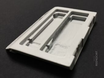
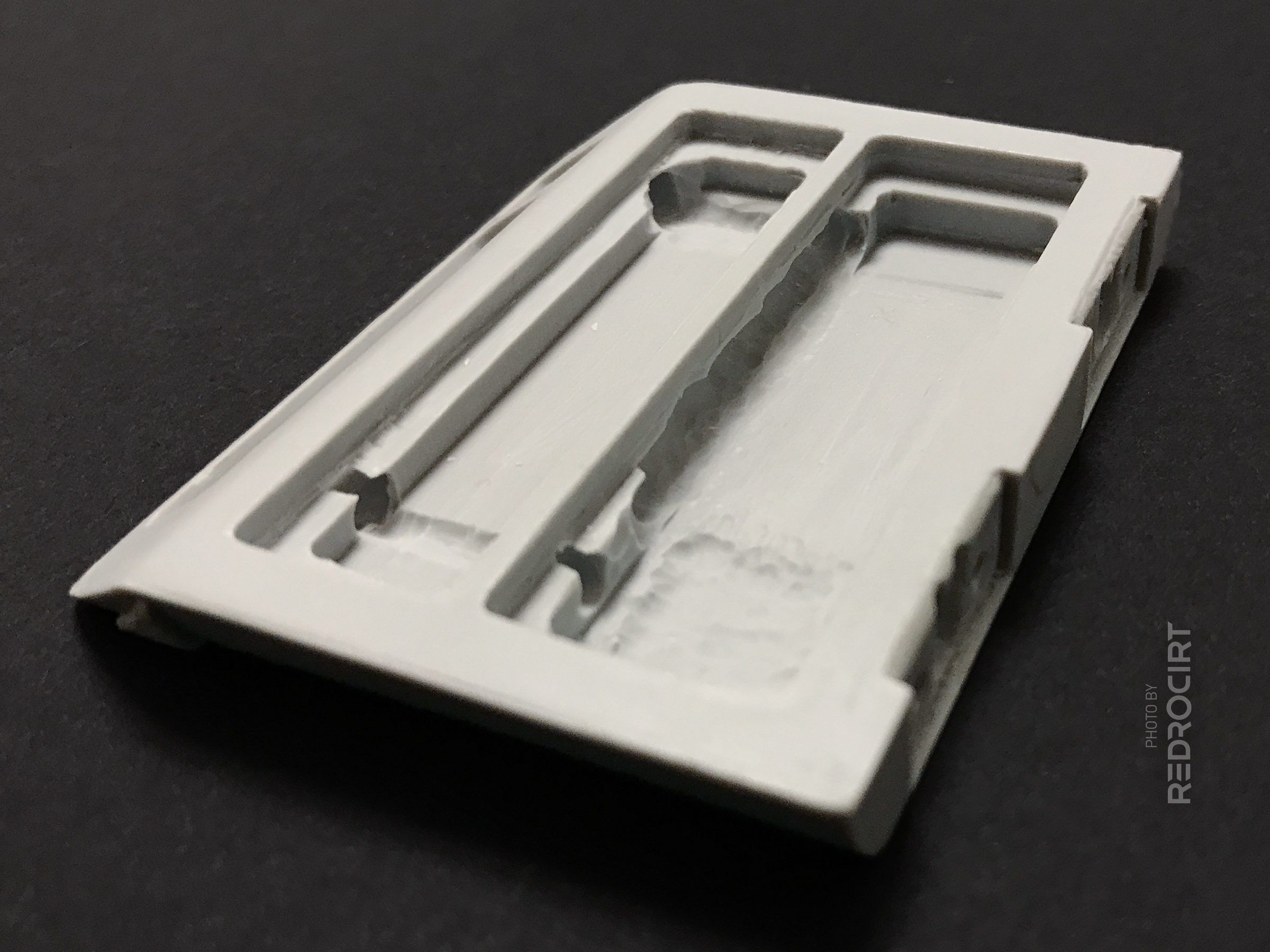
Carved depressions in the door 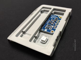
Also deepened the LED area 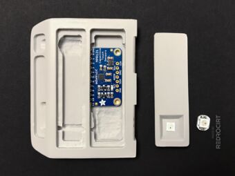
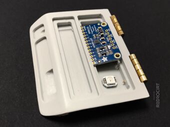
Breakout board fitting test 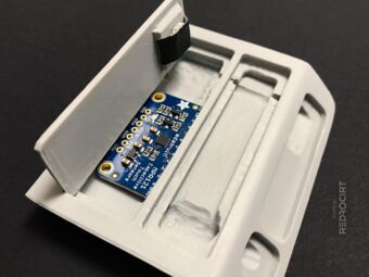
Test with the LED and lid 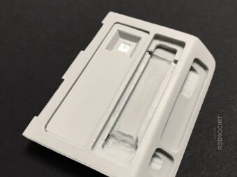
Closed lid: This should work!


Two breakout boards sharing one I2C bus
Section titled Two breakout boards sharing one I2C busAlthough I2C (Wikipedia) is a serial communication bus, the breakout boards are actually connected in parallel, not in series. That means both breakout boards are connected to the same SCL (serial clock line) and SDA (serial data line) GPIOs. Below is a wiring example similar to my test setup.
Note: If several breakout boards are connected to one I²C bus, their pull-up resistors are connected in parallel and decrease the total resistance. This can become problematic if you add too many breakout boards. More details here: How many devices can you connect to the I²C bus?
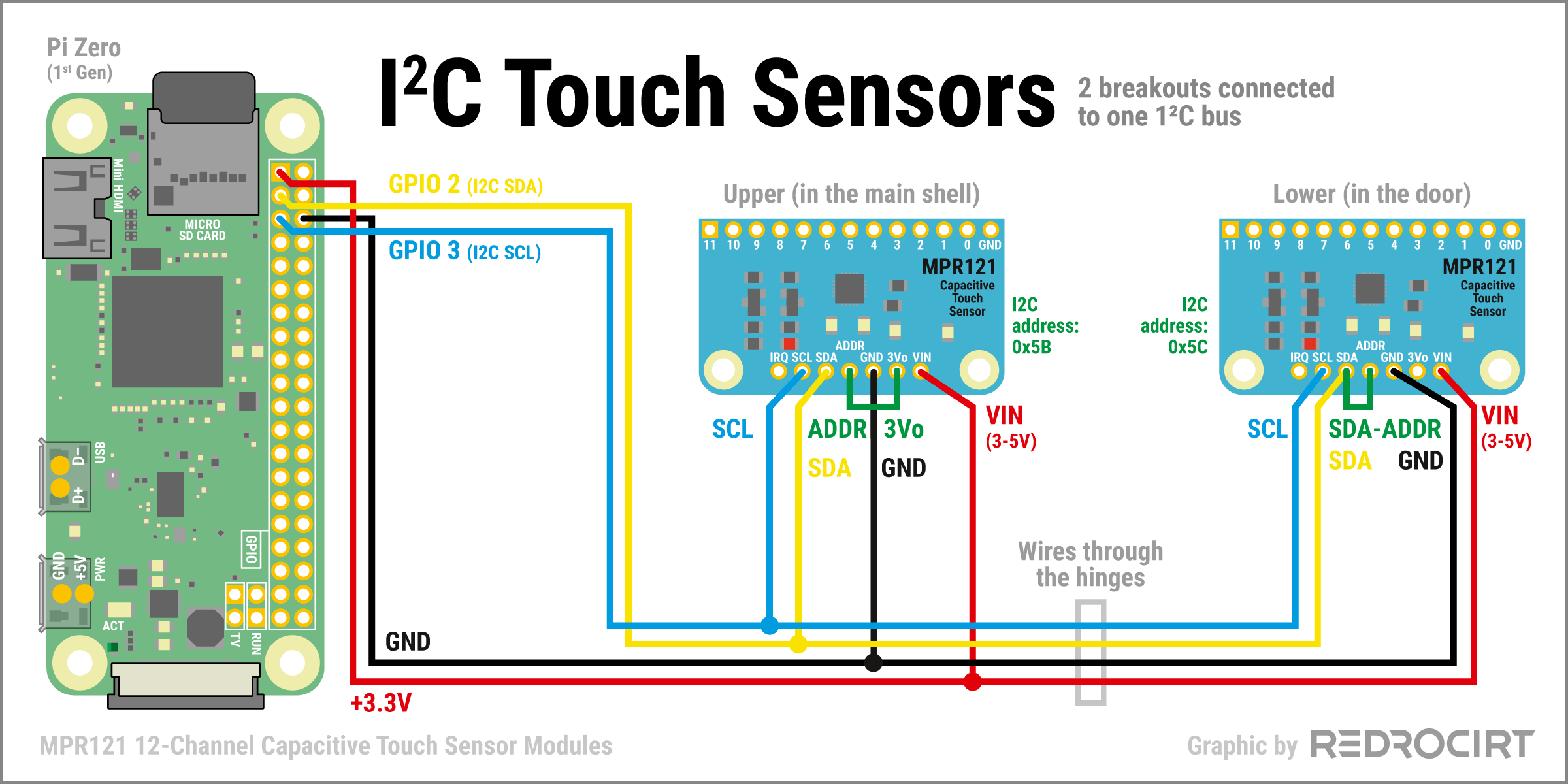

- In my current test setup, four wires need to go from the main body through the hinges and into the door: +3.3V, GND, SDA and SCL
The MPR121 breakouts I used support four different I²C addresses.
- On the first (upper) breakout I connected ADDR with the 3Vo pin for an address of 0x5B.
- On the second (lower) breakout I connected ADDR with the SDA pin for an address of 0x5C.
Enable I2C interface for touch sensors
Section titled Enable I2C interface for touch sensorsNote: Some driver information in this article may be out of date.
Instructions from Adafruit to enable I2C
- If not already done: first install the helpers:
sudo apt-get install -y python-smbus
sudo apt-get install -y i2c-tools- Then connect e.g. via Putty (SSH) and enable the interface. Command to open configuration:
sudo raspi-config- Use arrow keys to go to 3 Interfacing Options, confirme with ENTER key
- Use arrow keys to go to P5 I2C, confirme with ENTER key
- Question "Would you like the ARM I2C interface to be enabled?": Select YES, confirme with ENTER key
- Confirme changes once again with OK
- Back in the settings overview: Use tabulator key to jump to the bottom menu, select FINISH and confirme with ENTER key
- Question "Would you like to reboot now?": Select YES, confirme with ENTER key
- Reboot
Since the touch sensors are already connected, you can check whether they are detected after the reboot. To do this, I connected again via Putty/SSH and entered the following command in the console:
sudo i2cdetect -y 1The two MPR121 modules should be displayed with the defined addresses 0x5B and 0x5C.
.    0  1  2  3  4  5  6  7  8  9  a  b  c  d  e  f
00: -- -- -- -- -- -- -- -- -- -- -- -- -- -- -- --
10: -- -- -- -- -- -- -- -- -- -- -- -- -- -- -- --
20: -- -- -- -- -- -- -- -- -- -- -- -- -- -- -- --
30: -- -- -- -- -- -- -- -- -- -- -- -- -- -- -- --
40: -- -- -- -- -- -- -- -- -- -- -- -- -- -- -- --
50: -- -- -- -- -- -- -- -- -- -- -- 5b 5c -- -- --
60: -- -- -- -- -- -- -- -- -- -- -- -- -- -- -- --
70: -- -- -- -- -- -- -- -- -- -- -- -- -- -- -- --
Using the MPR121 touch sensors in Python
Section titled Using the MPR121 touch sensors in PythonWhen I added the first MPR121 breakout to my setup, I simply followed the documentation for wiring and installation of the MPR121 library, as well as the example code to use the MPR121 module in Python. To install the MPR121 library (GitHub) just enter this in the console:
sudo pip3 install adafruit-circuitpython-mpr121If a second breadout board is connected to the I²C bus, you simply need to add the I²C address to the initialization code and add a second initialization for the second breakout. Here is a simplified example:
# Import libraries
import board
import busio
import time
import RPi.GPIO as GPIO
import adafruit_mpr121

# Create I2C bus
i2c = busio.I2C(board.SCL, board.SDA)

# Create two MPR121 objects with specified I2C addresses
mpr121_a = adafruit_mpr121.MPR121(i2c, address=0x5b)
mpr121_b = adafruit_mpr121.MPR121(i2c, address=0x5c)

# Helper variable to prevent input signal spam
touchdelay = False

try:
  while True:
      # get current state of all pins
      touched_a = mpr121_a.touched_pins
      touched_b = mpr121_b.touched_pins
      # only execute when touchdelay is deactivated
      if touchdelay == False:
          # First touch module
          if touched_a[0]:
              print('A0 touched')
              touchdelay = True
          elif touched_a[1]:
              print('A1 touched')
              touchdelay = True
          elif touched_a[2]:
              print('A2 touched')
              touchdelay = True
          elif touched_a[3]:
              print('A3 touched')
              touchdelay = True
          elif touched_a[4]:
              print('A4 touched')
              touchdelay = True
          elif touched_a[5]:
              print('A5 touched')
              touchdelay = True
          elif touched_a[6]:
              print('A6 touched')
              touchdelay = True
          elif touched_a[7]:
              print('A7 touched')
              touchdelay = True
          elif touched_a[8]:
              print('A8 touched')
              touchdelay = True
          elif touched_a[9]:
              print('A9 touched')
              touchdelay = True
          elif touched_a[10]:
              print('A10 touched')
              touchdelay = True
          elif touched_a[11]:
              print('A11 touched')
              touchdelay = True
          # Second touch module
          if touched_b[0]:
              print('B0 touched')
              touchdelay = True
          elif touched_b[1]:
              print('B1 touched')
              touchdelay = True
          elif touched_b[2]:
              print('B2 touched')
              touchdelay = True
          elif touched_b[3]:
              print('B3 touched')
              touchdelay = True
          elif touched_b[4]:
              print('B4 touched')
              touchdelay = True
          elif touched_b[5]:
              print('B5 touched')
              touchdelay = True
          elif touched_b[6]:
              print('B6 touched')
              touchdelay = True
          elif touched_b[7]:
              print('B7 touched')
              touchdelay = True
          elif touched_b[8]:
              print('B8 touched')
              touchdelay = True
          elif touched_b[9]:
              print('B9 touched')
              touchdelay = True
          elif touched_b[10]:
              print('B10 touched')
              touchdelay = True
          elif touched_b[11]:
              print('B11 touched')
              touchdelay = True
      # Wait 3 seconds to avoid multiple inputs at same time, then reset
      elif touchdelay == True:
          print('PAUSE 0.5 Sec')
          touchdelay = False
          sleep(0.5)
      # Small delay between input scan
      else:
          sleep(0.25)

except KeyboardInterrupt:
  print('Program manually interrupted. GPIO cleanup')

finally:
  GPIO.cleanup()
I added the variable touchdelay to avoid multiple inputs at same time. I also added GPIO.cleanup() at the end in case the program is interrupted. More about GPIO.cleanup() in this article: How to exit GPIO programs cleanly, avoid warnings and protect your Pi (RasPi.tv).