Disclaimer: I am not an expert in electronics or programming. That's the way I did it, and that's not necessarily the correct way to do it.
Detection of the status of the lower door
Section titled Detection of the status of the lower doorThere are two reasons why I wanted to be able to detect if the bottom door is open or closed:
- Magic activation: Back in the nineties, it was unusual and quite impressive (at least for me) that the Tricorder turned on immediatly when the user opened the bottom door. Today, to activate your smartphone, all you need to do is lift it or tap the touchscreen, or sometimes a glance is enough. How far we have come... In my replica, all LEDs, sound effects and the screen should turn on when the bottom door is opened. When the door is fully closed, everything should be switched off. The Raspberry Pi needs some time to boot up and to shut down the system properly, so this cannot be a real power switch. Instead I'm just triggering a standby/sleep mode in the Python script.
- Iconic ratchet sound: The first TR-560 props had a mechanical ratcheting opening mechanism, probably similar to this (YouTube). In later versions of the prop, this mechanism was removed, but the iconic ratcheting sound when opening and closing the door remained (added in post production, like most of the sound effects, the props generally had no sound). In my replica, the ratchet sound should be triggered when the door is opened and at the moment when you start closing the door.
Using reed switches with magnets
Section titled Using reed switches with magnetsIn looking at the electronics of others, I have found that many of them use two reed switches (Wikipedia) that open or close the circuit when a magnet is brought near or removed:
- One reed switch is placed in the main shell close to the upper I/E buttons. The corresponding magent is located in the door at the bottom, behind the nameplate. This reed switch is triggered by the magnet when the door is completely closed.
- The second reed switch is located in the main shell on the side wall between the two hinges. The corresponding magent is placed in the thin side wall of the bottom door, also between the two hinges. This reed switch is triggered when the door is fully open.
Some additional notes:
- I later thought about adding a magnetic USB power plug. Unfortunately, this magnetic plug triggered the reed switch near the hinges, so I couldn't use the magnetic USB plug in my build.
- Reed switches with magnets should not be used if you want to detect magnetic fields with a magnetometer sensor in your device and the magnetic fields can also interfere with other devices.
- At the time, I didn't look for alternatives. You could also use hall effect sensors (Wikipedia), proximity sensors or maybe even something like pogo pin contacts (Wikipedia).
Connecting magnetic switches to Raspi’s GPIO
Section titled Connecting magnetic switches to Raspi’s GPIOFirst of all, I highly recommend reading the Beginners Guide to Wire Things to the GPIO (Raspberry Pi Forums). This article contains many important hints what to consider when connecting hardware to the GPIOs of the Raspi. There is also a very helpful illustration with switch circuits after the safety advice in the chapter “What about fitting a switch to a GPIO pin?”.
It is important to add resistors (330 and 3.3K) to avoid short circuits and damage to the GPIO inputs. Here is an example circuit with reed switches, derived from the schematics in the linked article:
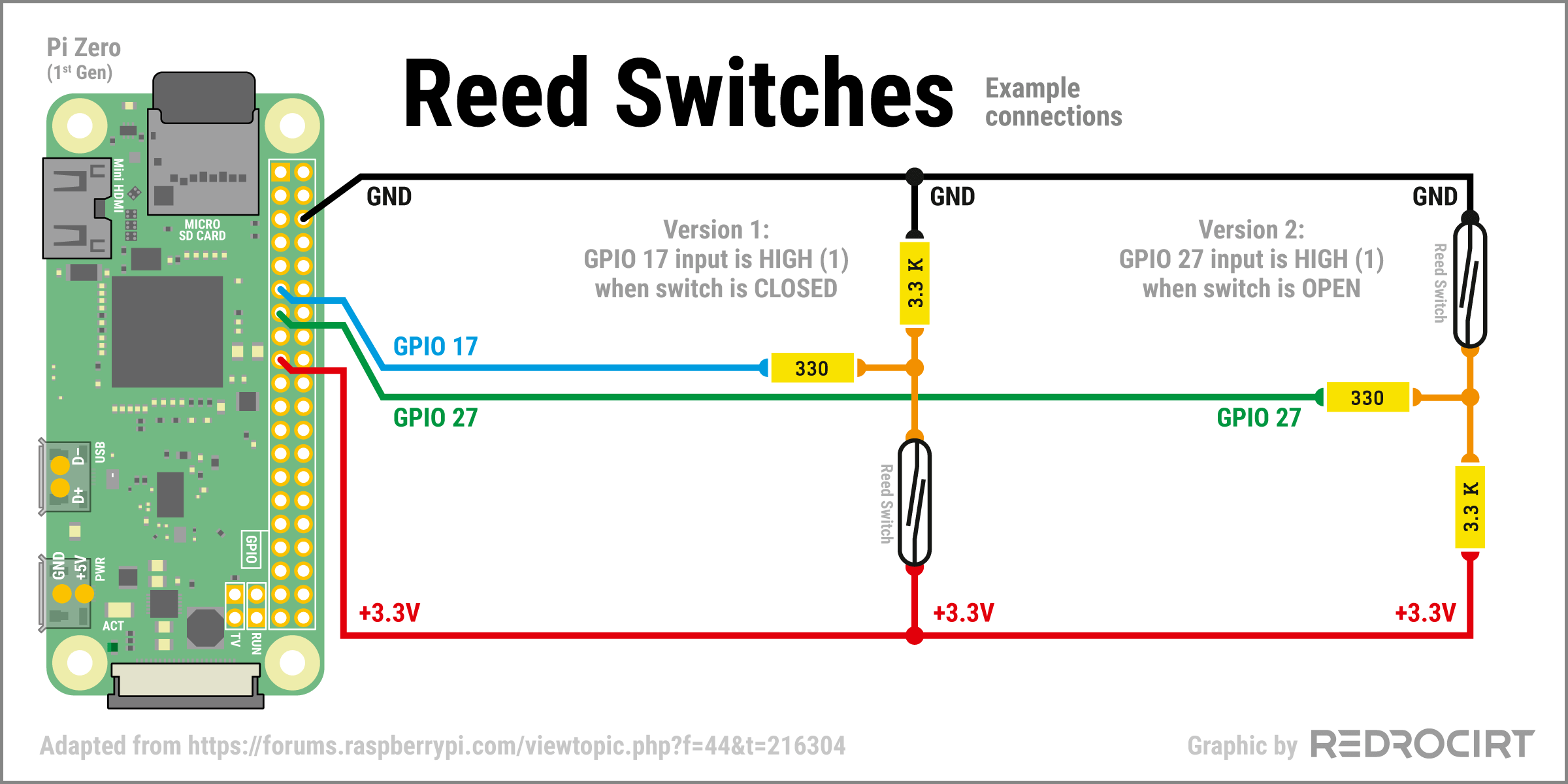

- Version 1: GPIO 17 is HIGH (1) when the reed switch is CLOSED (magnet nearby) and LOW (0) when the reed switch is OPEN (no magnet nearby). I'll use this version for the lower reed switch (which detects when you start to close the door). This will trigger the closing ratchet sound and turn off all LEDs and the screen (activate standby/sleep mode).
- Version 2: GPIO 27 is LOW (0) when the reed switch is CLOSED (magnet nearby) and HIGH (1) when the reed switch is OPEN (no magnet nearby). I'll use this version for the upper reed switch (which detects when the door is fully closed and when you start to open the door). This will trigger the opening ratchet sound and turn on all LEDs and the TFT screen (deactivate standby/sleep mode).
Note/Afterthought: You probably don't need both circuit versions. I'm not sure why I decided to include both versions in my build. It is possible to handle all functions with two identical reed switch circuits.
Hardware
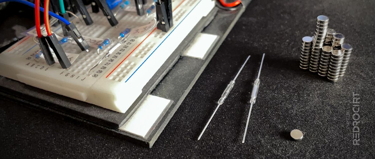
Section titled HardwareWhile searching for reed switches in online shops, I found that there are many different types and sizes. After some research I knew I wanted type SPST-NO Form A (single pole, single throw, normally open). I had no idea what AT (sensitivity) values I need, so I ordered different types (10-15 AT, 15-20 AT, 20-25 AT...). If I remember correctly, I ended up using 10-15 AT in my build, with approx. 14 mm length.
I already had 330 and 3.3K resistors at home. In addition, I ordered some small neodymium magnets (diameter 3mm, 1mm thick), which should easily fit into the small space between the hinges of the door.
Raspberry Pi configuration
Section titled Raspberry Pi configurationI added the configuration for GPIO 17 and GPIO 27 in the boot file, right at the top/beginning, so Raspi already knows during booting that these two GPIOs are input GPIOs with pull down resistors:
/boot/config.txt
# Reed switches
# GPIO 27 = upper reed switch
# GPIO 17 = bottom reed switch
# ip = input, pd = pull down
gpio=27=ip,pd
gpio=17=ip,pd
Usage in the Python script
Section titled Usage in the Python scriptAt the time, I just added the basic detection functions to my script and output to the console when a change was detected. This was sufficient to test the basic functionality of the reed switches. Shortened excerpt:
# Abridged excerpt from my main script with reed switch relevant code

# Import libraries
import board
import busio
import RPi.GPIO as GPIO # for reading/setting GPIO signals
import time # for timing control
# [... and other libraries ...]

# [...]

#############################################
# GPIO 17 = BOTTOM reed switch to detect when the door is completely open
# GPIO is HIGH when reed switch is CLOSED
# Set pin to be an input pin and set initial value to be pulled low (off)
GPIO.setup(17, GPIO.IN, pull_up_down=GPIO.PUD_DOWN)

# Pin 17 callback fucnction
def reed_switch_closing_callback(channel):

  txt_channel = str(channel)
  txt_high = "Bottom Reed switch GPIO {} chanced to HIGH – Fully opened".format(txt_channel)
  txt_low = "Bottom Reed switch GPIO {} chanced to LOW – Closing – Play sound".format(txt_channel)

  if GPIO.input(channel) == GPIO.HIGH:
    print(txt_high)
  else:
    print(txt_low)
    # ToDo: Play the closing ratchet sound
    # ToDo: Add a function to turn all LEDs and the screen OFF

# Pin 17 event detection
GPIO.add_event_detect(17, GPIO.BOTH, callback=reed_switch_closing_callback, bouncetime=300)

#############################################
# GPIO 27 = TOP reed switch to detect when the door is completely closed
# GPIO is HIGH when reed switch is OPEN
# Set pin to be an input pin and set initial value to be pulled low (off)
GPIO.setup(27, GPIO.IN, pull_up_down=GPIO.PUD_DOWN)

# Pin 27 callback function
def reed_switch_power_callback(channel):

  txt_channel = str(channel)
  txt_high = "Top Reed switch GPIO {} chanced to HIGH".format(txt_channel)
  txt_low = "Top Reed switch GPIO {} chanced to LOW".format(txt_channel)

  if GPIO.input(channel) == GPIO.HIGH:
    print(txt_high)
    # ToDo: Play the opening ratchet sound
    # ToDo: Add a function to turn all LEDs and the screen ON
  else:
    print(txt_low)

# Pin 27 event detection
GPIO.add_event_detect(27, GPIO.BOTH, callback=reed_switch_power_callback, bouncetime=300)

# [...]
About the same time I was experimenting with the reed switches, I took apart my first test board and built a completely new test rig, expanded to include all the new components...

