Note: Do not use magnets if you want to use a magnetometer or other sensors that are sensitive to magnetic fields in your setup. The position of the magnets and reed switches can also be problematic if you want to use a magnetic charging cable/port (which I unfortunately realized too late).
Adding magnets to hold the door closed
Section titled Adding magnets to hold the door closedThe brass hinges don't have much friction, so I decided to add small neodymium magnets to the frame of the door and the main shell to keep the door closed when it's closed. I drew marks on the sides so the magnets would meet, and then drilled 3.5 mm holes (the magnets I used have a diameter of 3 mm).
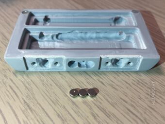
Drilled 4 holes for magnets 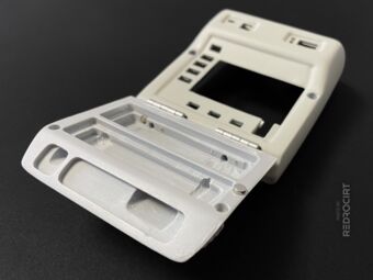
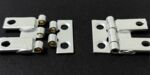
Magnet placed next to the hole 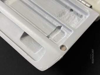
Magnet inserted in the hole


Then I glued the magnets in place with a drop of ultra-strong 2-component epoxy and let it dry. After a few hours, I applied a thicker layer of epoxy glue (in the main shell also from the back/inside) and then let it dry overnight. The next day I sanded the glue spots smooth (didn't take photos of it).
Filled the hole with epoxy glue 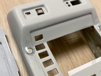
Magnet glued in the main shell 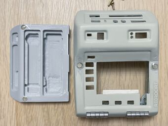
Magnets added to door and body


Note: The magnets I used aren't strong enough to hold the weight of the door when you turn the closed Tricorder upside down. I recommend using stronger or larger or multiple magnets to hold the door closed.
Adding magnets for the reed switches
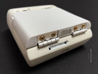
Section titled Adding magnets for the reed switchesI'm using two reed switches in my electronics to trigger functions depending on the status of the door. One reed switch (and associated magnet) is located between the hinges. Since I only had the small magnets on hand, I added three of them to the door after drilling holes for them between the hinges.
Drilled holes for three magnets 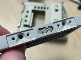
Inserted magnets in the holes 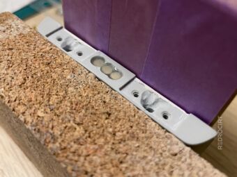
Glued the magnets in place


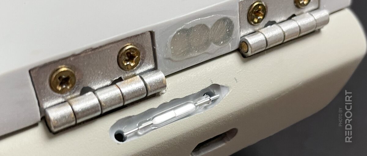
I carved a recess in the main shell for the lower reed switch. This recess is not exactly in the middle, but slightly offset to the left. As a result, the left hole for the cable feed-through into the interior is exactly in the center of the left hinge and does not interfere with the hinge screws.
Carved recess for the reed switch 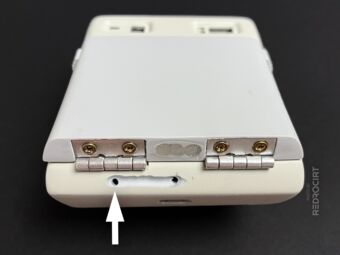
Left hole centered to the hinge 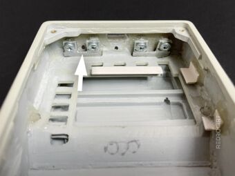
Hole for the wire between screws 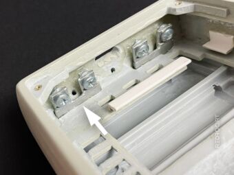
Inside view of the hinge area 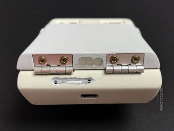
Fitting test with the reed switch 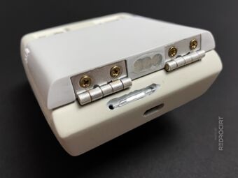
Magnets are offset to the reed switch


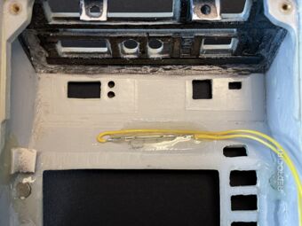
After soldering wires to the ends of the reed switch, I temporarily fixed it from the inside with hot glue. Then I applied 2-component epoxy from the outside to fix it permanently and fill the gaps. After the epoxy glue had dried overnight, I carefully removed the hot glue inside and sanded the epoxy glue outside smooth.
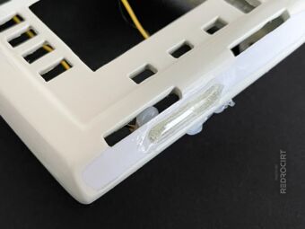
After applying the epoxy glue 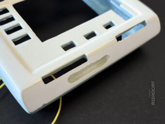
After sanding the epoxy flat 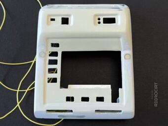
Also sanded upper magnet areas


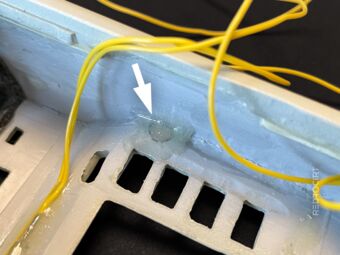
I also glued the black USB socket housing back in place and fixed the yellow reed switch cables inside with epoxy. Later I also glued the second reed switch to its position behind the slanted buttons above the display. I decided to glue the reed switches in permanently, even though I might regret it.
Glued the upper reed switch 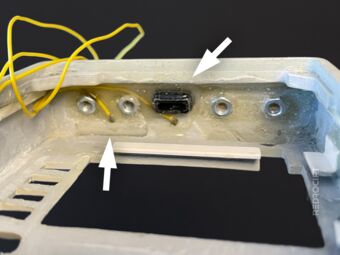
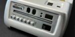
Wires and USB housing in place 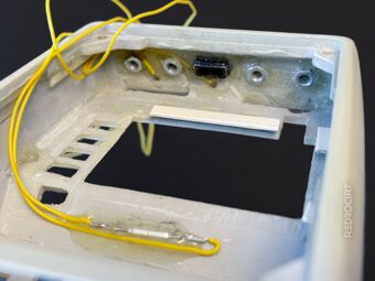
Inside view with reed switch wires


Initially, I had positioned the magnets for the upper reed switch in the middle of the lower side of the door, in the area of the nameplate. After the reed switch was glued in place, I did a simple functional test with an LED and found that the reed switch did not respond to the magnets. So I removed the magnets in the door again and glued them a little further to the right in the already existing hole. Thus the reed switch worked.
Centered position didn't work 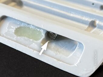
Right position worked 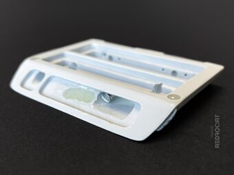
Holes filled with expoy


Minor other work
Section titled Minor other workInside the main shell, I later used a high-speed cutter and sandpaper to remove some of the epoxy I had used to glue the side magnets (that hold the door closed). This was necessary so that the TFT display can be pushed in flat and so that there is enough space for the alpha-to-delta lights on the other side. (I only took close-up pictures before, not after the removal/sanding...)
Had to sand the epoxy flat 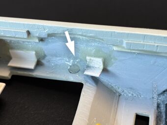
Due to the epoxy layer, the TFT... 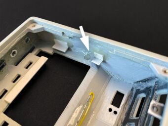
...could no longer be inserted


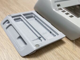
Reverting modifications on the back lid
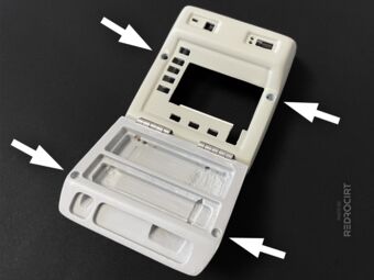
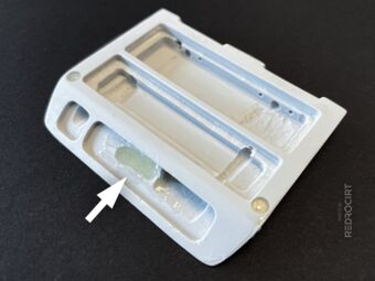
Section titled Reverting modifications on the back lidWhen I started the project, I had modified the scanner pocket thinking that I would position the touch sensor breakout and main power switch on the front of the scanner pocket. This idea is now obsolete. The DotStar Matrix and NeoPixel stick are located in the front area, there is no room for other things there. So I removed the screw nuts on the scanner pocket again and closed the main switch hole with epoxy.
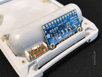
This placement is obsolete 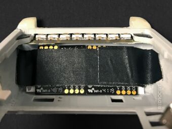
Space required for the LED boards 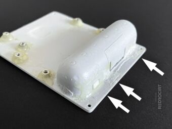
Filled the hole and removed nuts 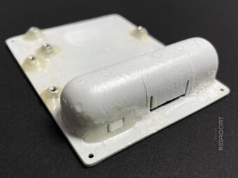
Left side: Filled main switch hole 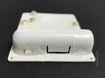
Center and right: Removed nuts 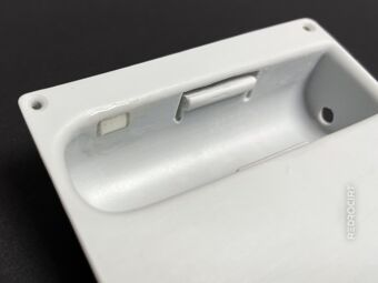
View inside the scanner pocket


Note: I later replaced the back lid and changed from a Mark X to a Mark IX (without a scanner pocket).