SMD RGB LED boards for the front
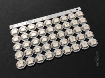
Section titled SMD RGB LED boards for the frontWhile looking for flat LEDs for the scanner front, I came across small 8×8 grid matrix boards. These are only about 25×25 mm and because of the tiny SMD LEDs only 2.6 mm thick. Each LED has an embedded microcontroller and acts like a shift register. Data and clock can be controlled by SPI or bit banged.
One matrix has 64 LEDs, for the scanner front two modules fit next to each other. The mounting holes can be easily snapped off and you can daisy chain the boards. Of the total 128 LEDs only a small area will be visible later, but at least I don't have to create my own PCB, I don't have to solder SMD components and it's very compact. The “Dotstar” LEDs are multicolored (RGB) and can be controlled individually.
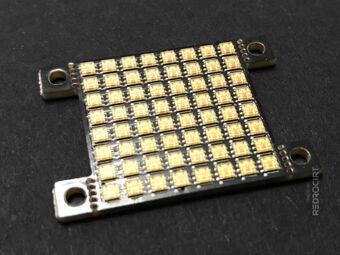
8×8 SMD LED matrix PCB 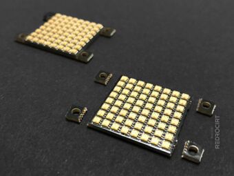
Snap off the mounting holes 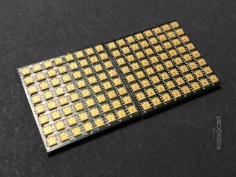
Two LED PCBs side by side 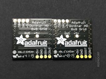
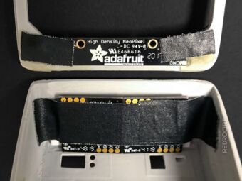
Rear view of the LED matrix PCBs 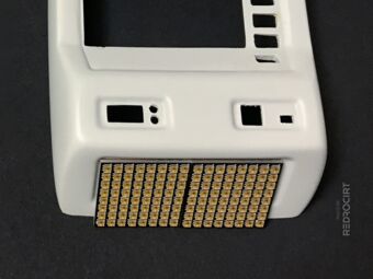
LED PCBs in front of the shell 
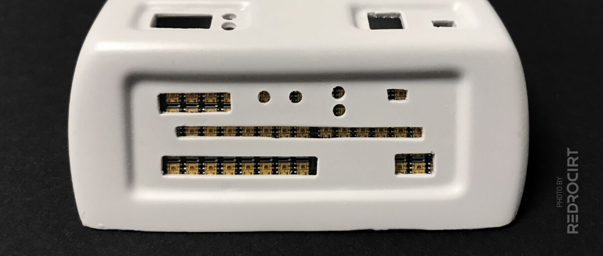
LED PCBs inside the shell


The LED positions do not match the existing LED cutouts in the shell, but that's not a problem because I'm going to replace the front part of the scanner with a custom piece of laser-cut acrylic. I already have an acrylic panel, but I need to change the design of the part to fit better on the grid of the new LED boards.
RGBW LED stick for the bottom scanner array
Section titled RGBW LED stick for the bottom scanner arrayIt's almost embarrassing that I didn't know about LEDs with integrated microcontrollers earlier, even though they come in so many different types and sizes. After reading the product descriptions and instructions, I will definitely be using these and replacing some of the “oldschool” LEDs in my build.
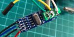
For the lower scanner array I ordered a “NeoPixel Stick” with 8× 5050 RGBW LEDs (with natural white ~4500K). The size of this stick is almost perfect, I just had to enlarge the gaps in the frame and file away some parts on the shell (basically make the wall a little thinner).
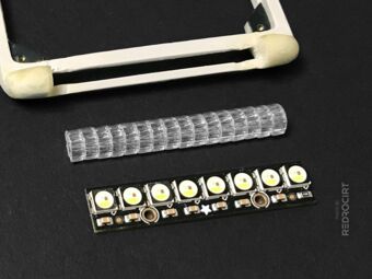
LED stick for the lower scanner 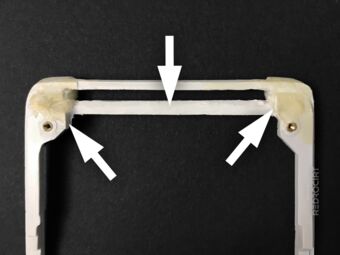
Filing some parts of the frame 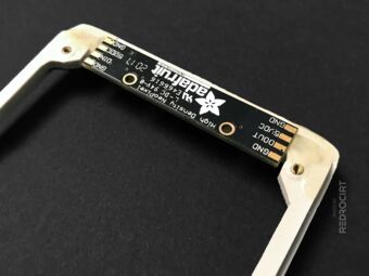
Test fitting the LED stick 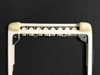
LEDs are only partially covered 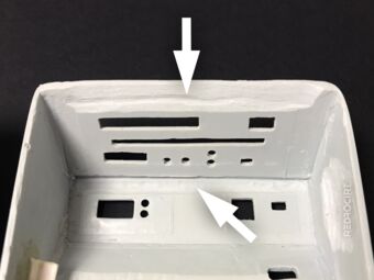
Filing depressions in the shell 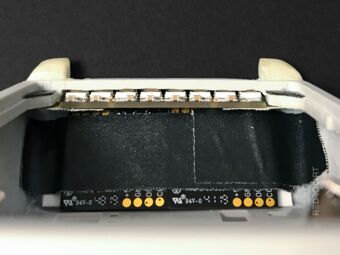
It's a tight fit... maybe too tight?


I temporarily fixed the LED panels with tape to test the fit of the parts. When the frame is placed on the shell, the LED stick and the LED matrix boards almost touch each other. This is not good because the solder joints on the back of the boards are too close together.
LED panels fixed with tape 
Placing the frame on the shell 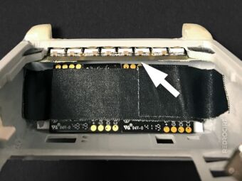
Required gap between the boards 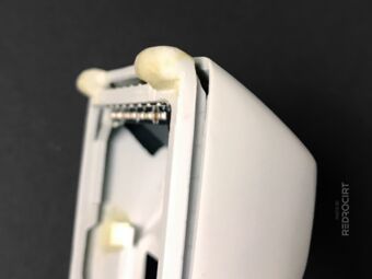
This would be the required distance 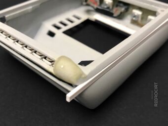
Using ABS profiles as spacers 
Test fitting ABS spacer


I need a small gap between the boards for the solder connections and to avoid short circuits. I will therefore increase the height of the shell slightly and glue in 3mm thick ABS profiles on all sides. This also creates a bit more space inside the body for the other electronics and the battery.
And more LEDs...
Section titled And more LEDs...I had also ordered single 5050 RGB LEDs prepared on a small board with SMD resistor, capacitor and solder pads on the back. I'm going to replace the solid green "Sequin" LEDs for the Alpha-to-Delta ("ABGD") lights, and have prepared a set of four RGB LEDs for testing. The PCB diameter is a bit too large, so I carefully filed down the sides to make it more compact.
Small LED PCBs (“buttons”) 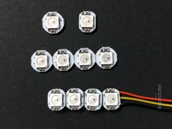
Separated and reduced width 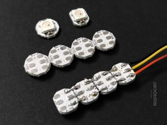
Connected four in a row 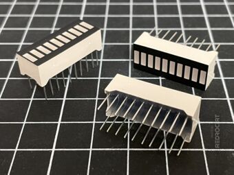
10 segment LED light bar graphs 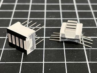
Sawed into two parts 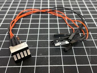
Split LED bar prepared for testing


And I had ordered a couple of one-colored 10 segment LED light bar graphs, in green and yellow. I wasn't sure yet if I would use them in my build, but I wanted to test if they could be split (yes, I just sawed them in half) and how well the individual LEDs are separated from each other (to avoid light bleed). I thought these LED bars might be an option for the top left and right positions in the main body...