Last acrylic elements for the front
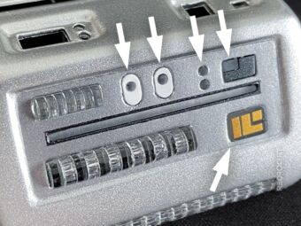
Section titled Last acrylic elements for the frontAfter I had painted the case metallic, I had already added most of the greebles to the front. Before I could install the LED matrix panels, the last missing acrylic parts had to be added: I shortened some acrylic rods with a diameter of 2 mm and fitted them into the round holes in the front panel. The ends of each piece are sanded to improve light diffusion. Then I glued the round rods from the inside with epoxy in place.
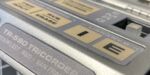
The two rectangles for the cutouts on the right side (which will be backlit red/yellow) are made of frosted acrylic glass (same as the EMRG button), and were also glued in place with epoxy. The “IL°” stickers are made of gold/bronze adhesive foil. With this, the outside of the front scanner panel was completed.
Last acrylic parts for the front 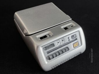
Finished outer front panel 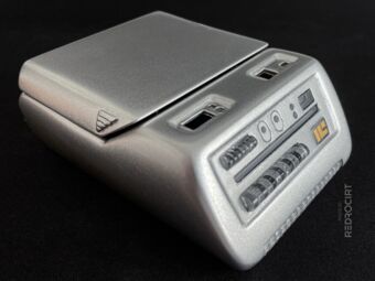
Self-made with custom parts


New LED numbering for rotated DotStar Matrix
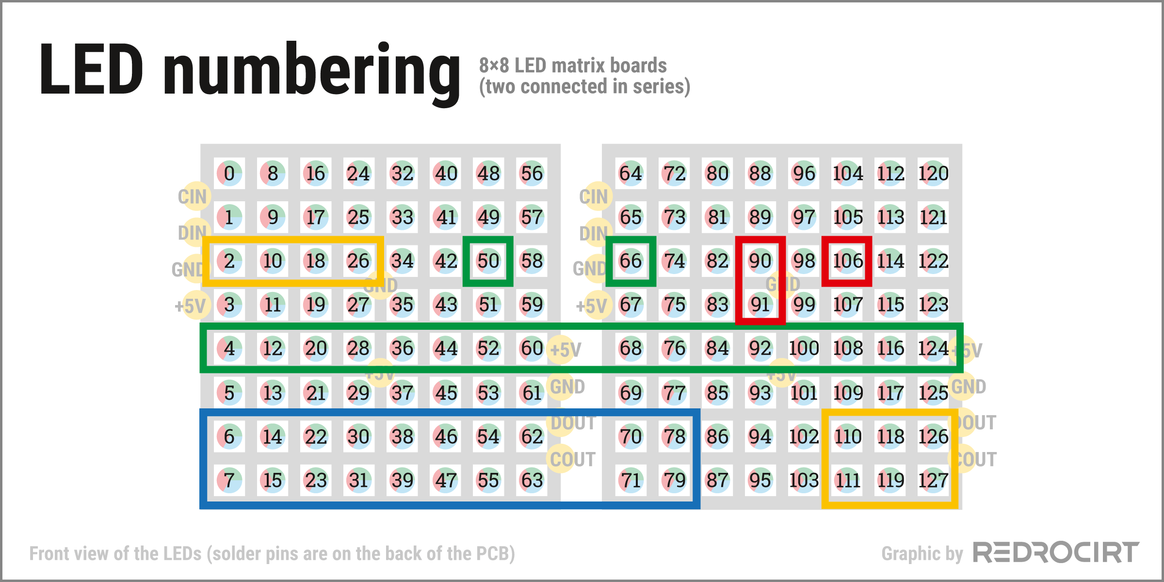
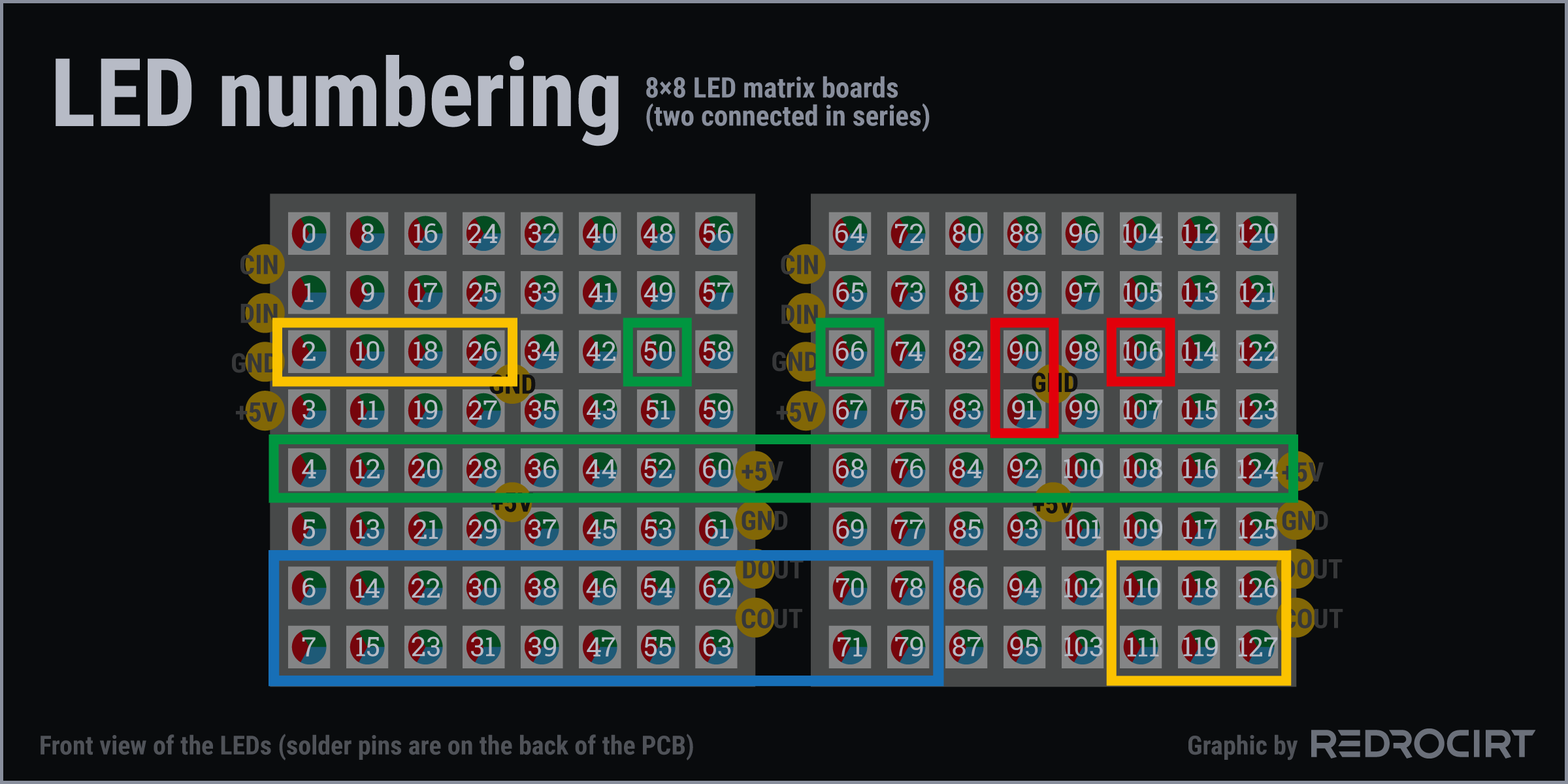
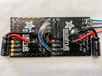
Section titled New LED numbering for rotated DotStar MatrixNext, I wanted to prepare the two DotStar 8×8 matrix boards (multicolor LED panels) for installation. From my fitting attempts a while back, I knew it was going to be a tight fit with soldered wires (although I had since increased the height of the main shell).
I decided to rotate the boards so that the solder points were on the sides (instead of top/bottom). Since this changed the numbering of the LEDs, I updated my old sketch with the numbers (new version below) and also had to update all code snippets in my Python scripts where these numbers are used.
Preparing the LED panels for installation
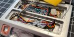
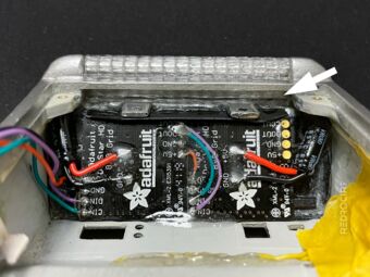
Section titled Preparing the LED panels for installationTo keep the setup flat, I bent the legs of the capacitors and positioned them on the sides. After insulating the legs with heat shrink tubing, I soldered them to the PCBs and connected both matrix boards with wires (schematic). Finally, I added some epoxy glue as additional insulation and to fix the parts in place.
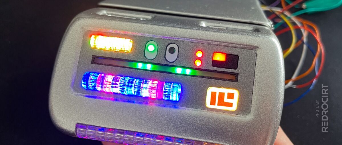
After that, I connected the LED boards to my test rig and hold them into the case to test the positioning. Although I had already added partitions on the back of the front panel, there was still some light bleed visible from the LEDs of the middle green scanner bar. Therefore, I added a thin black ABS strip.
Capacitors on the sides 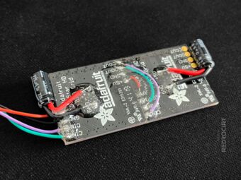
Added epoxy glue for insulation 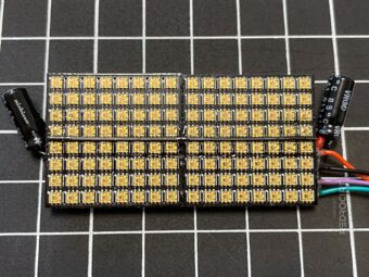
Thin stripe of black ABS... 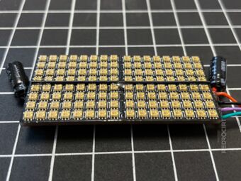
... to further reduce light bleeding 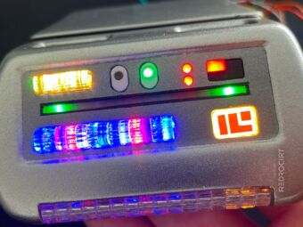
Temporary fitting test 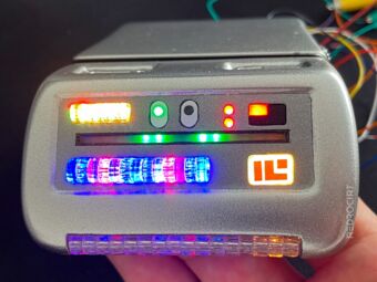
Bottom acrylic row shouldn't be lit


Installing the DotStar matrix boards
Section titled Installing the DotStar matrix boardsThere was still some light bleeding visible in the lower acrylic row (bottom scanner bar). To prevent this, I cut another black ABS stripe into shape to serve as a separator between the matrix boards and the NeoPixel stick. After some testing I glued the matrix boards and the black separator in place.
Gap for the NeoPixel stick 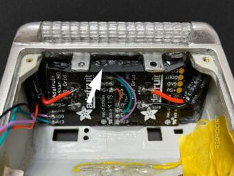
ABS stripe to reduce light bleeding 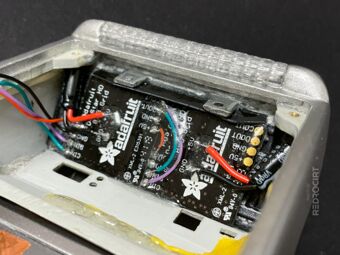
DotStar matrix glued in place 
Inserting the NeoPixel stick 
NeoPixel stick in place 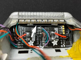
Separator to prevent light bleeding