Preparing a RGBW NeoPixel for the “ID” light
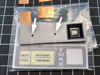
Section titled Preparing a RGBW NeoPixel for the “ID” lightI had filed the hole for the “ID“ light a little larger and had painted it white, so that the LED light is better reflected. The PCB of the RGBW NeoPixel Button is too large and can only be used lying flat. Thus I had desoldered the NeoPixel and soldered wires to the contacts to be able to get it in the correct position.
Painted the “ID” hole white 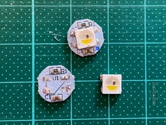
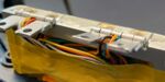
Desoldered the NeoPixel LED 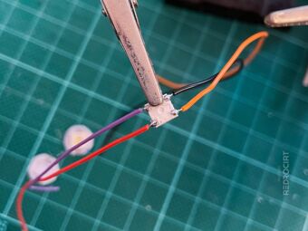
Soldered wires to the NeoPixel 
Soldered wires to the PCB 
Position of the NeoPixel and PCB 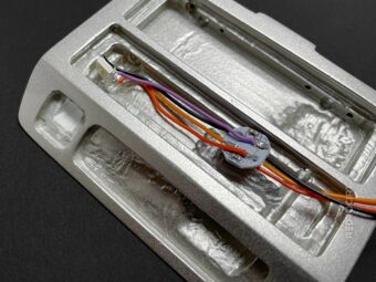
Fitting test with the NeoPixel


Preparing the MPR121 capacitive touch breakout
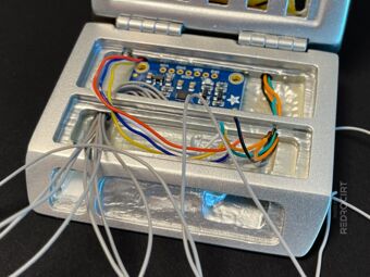
Section titled Preparing the MPR121 capacitive touch breakoutThe MPR121 touch breakout board in the door has 12 channels, so all keys in the door could be designed as capacitive touchpads (actually only 8 are used/required in the door). I had already soldered grey wires to the touchpins and fed the wires through the holes in the variuos sections.
Now I could solder the data and power wires (coming through the hinges) to the capacitive touch breakout board. I also connected ADDR with the SDA pin for an I²C address of 0x5C. I extended the power supply lines (+5.0V and GND) to use them for the NeoPixel LEDs as well.
Grey touch wires fed through hole 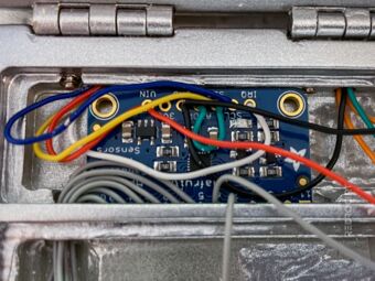
Soldered data and power wires 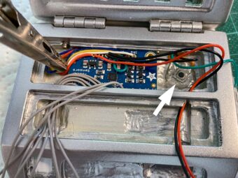
Added EMRG push button


The orange wires (coming through the right hinge) are used for a flat push button below the EMRG NeoPixel. I soldered the wires to the push button and carefully glued it in place with a strong 2-component epoxy.
Preparing the “ID” touchpad
Section titled Preparing the “ID” touchpadThe TR-590 kit came with a transparent, laser-cut acrylic square for the “ID” recess. To avoid light-bleed at the corners, I wanted only the square light area to be transluscent. Therefore, I drilled a hole in the acrylic and filed it to form a square. I spray painted this “frame” part to make it opaque. For the LED area, I filed transparent acrylic into shape and lightly sanded it to give it a milky surface (to distribute the light evenly).
To make also the ID key as a touchpad, I drilled a small hole to pass the touch wire through next to the light hole. Finally, I added copper foil and pushed the elements in place.

Door with acrylic parts 
Prepared acrylic for the ID light 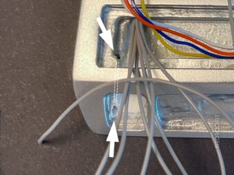
Drilled a hole for the touch wire 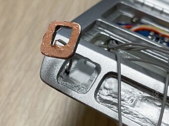
Added copper foil as touchpad 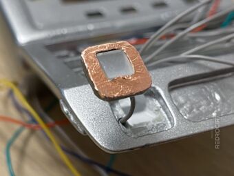
Added the translucent acrylic 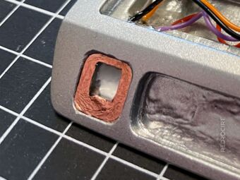
ID touchpad later in place


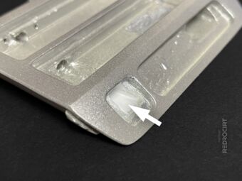
Later I realized that the ID recess should be a little deeper, so I removed the ID elements again. Fortunately, it wasn't attached with glue so I was able to remove it, but it was still difficult to get it out. I used a sharp knife and a file to remove some material behind it and pushed the ID elements back into place.
Preparing a RGBW NeoPixel for the “EMRG” light
Section titled Preparing a RGBW NeoPixel for the “EMRG” lightFor the “EMRG” light I also unsoldered a NeoPixel from the RGBW NeoPixel Button PCB. I sawed out a small rectangle from a piece of frosted acrylic (with a height of ~5mm) and sanded it from all sides to fit through the cutout in the lid of the button section. Then I glued this acrylic glass piece onto the NeoPixel.
Note: I chose a white/uncolored acrylic for the EMRG light. In the TV series, this light is always red and other replicas mostly use a red greeble. But since I have an RGBW NeoPixel behind it, I can make it glow any color if I want.
Of course, it didn't work on the first try. The acrylic glass had slipped during drying and the height wasn't quite right. So I repeated the steps and created another elongated EMRG light.

First acrylic test (not glued) 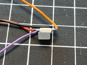
Failed gluing attempt 
Left: Failed (old); Right: Better (new)


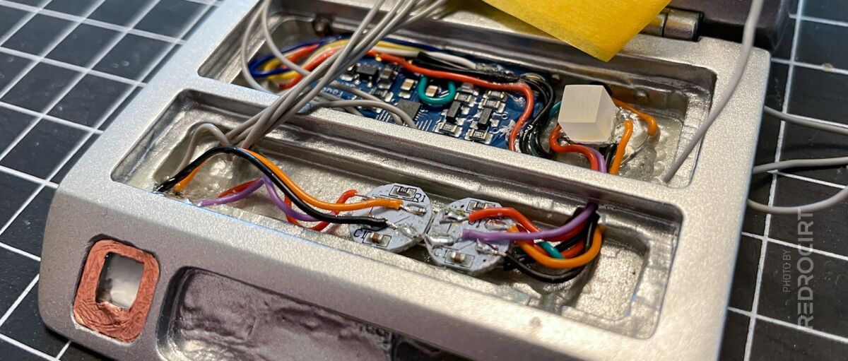
Then I could connect the two NeoPixel Button PCBs (ID and EMRG lights) and also solder the NeoPixel wires to the boards. I did some installation tests and glued the “ID” NeoPixel in place. The NeoPixel PCBs and the elongated “EMRG” NeoPixel remained loose.
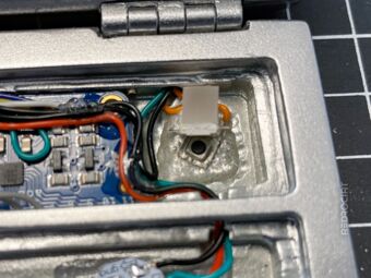
Push button below NeoPixel 
NeoPixel above push button 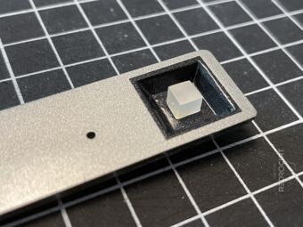
EMRG light in the button lid 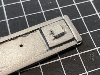
NeoPixel from below in the lid 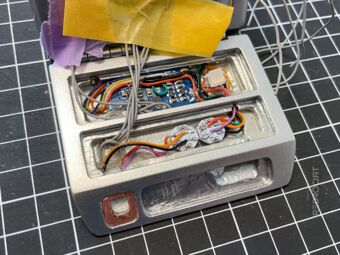
NeoPixels and PCBs connected 
ID light glued in place


Adding the copper tape touch pads
Section titled Adding the copper tape touch padsI drilled little holes in the button area lids to feed the touch wires through to the surface. For the touchpads I used simple copper tape, which I stick on the spreaded strand ends. In between I did some function tests by connecting the wires (that are guided through the hinges to the main shell) to my test rig.
Drilled holes for the touch wires 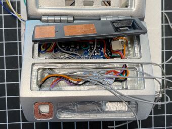
Added copper foil as touch pads 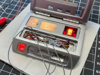
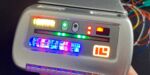
Testing the NeoPixels 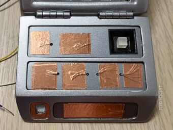
Added more copper foil touch pads 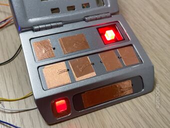
Wires connected to the test rig 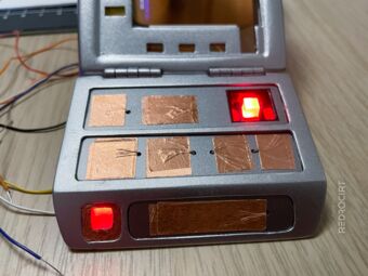
Function test of the touch buttons