Before I could apply the user interface (UI) stickers (or “labels”?) to my TR-590 build, I first had to...
Touch up the paint on the door
Section titled Touch up the paint on the doorUnfortunately, I had damaged the paint in several places when I installed the electronics in the door. I removed the lids in the touch button areas and carefully roughened the surface with sandpaper. Then I taped off the main body and electronics and sprayed the door and hinges again metallic silver.
Blemishes and paint damage 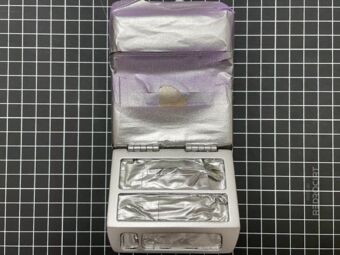
After a new coat of silver metallic 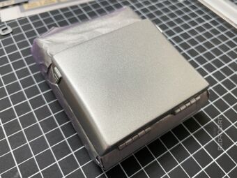
Also repainted the outside 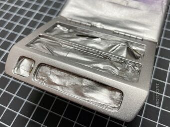
Waiting for the paint to dry... 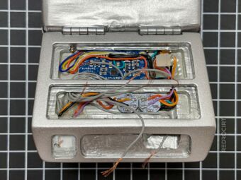
Carefully removed the tape 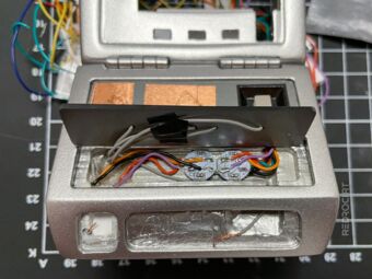
Added touch button lids again


Preparing the user interface graphics
Section titled Preparing the user interface graphicsI drew the sticker graphics in Illustrator, based on various photos of Tricorder props you can find on the internet, with minor adjustments for my replica. Then I printed out the graphics on regular paper, cut them out with a paper knife, placed them on the shell and adjusted sizes and colors in my drawings.
I repeated these steps until I found the right sizes and shapes for all the individual elements. Finally, I printed the graphics with crop marks on DinA4 labels (inkjet special paper, white, matte, photo quality, permanent) with a high resolution inkjet photo printer and let the prints dry for several hours.
Note: I tried different inkjet label papers (glossy too, but that didn't look good), and it took me a while to find the right settings in the printer software, because my inkjet printer has weird color management.
Transparent plastic membrane
Section titled Transparent plastic membraneDuring my research I came across the pictures of a beautiful replica of a medical TR-580 Tricorder VII on the RPF (photos here and here). The creator of this replica printed the graphics directly onto plastic membrane sheet. I really like the high-quality look of these labels, especially the surface texture.
I ordered two types of transparent binding covers (usually used for book binding, like e.g. theses/dissertations) – that was a mistake, they had a smooth, glossy surface on both sides with a lot of reflection. Luckily, I found a local shop that was selling single sheets of translucent PP (Polypropylene) in different types (with anti-reflex coat, 0.5/0.7/1mm thick). These PP plastics looked promising, one side was smooth and the other side with anti-reflective coating had the slightly rough surface texture I wanted.
I tried printing directly onto these plastics, but of course the ink did not dry on this material. In my search for alternatives, I came across a transparent adhesive film that adhere strongly on both sides. I printed the graphics on regular label paper and stick the PP plastic cover on top with the transparent adhesive film...
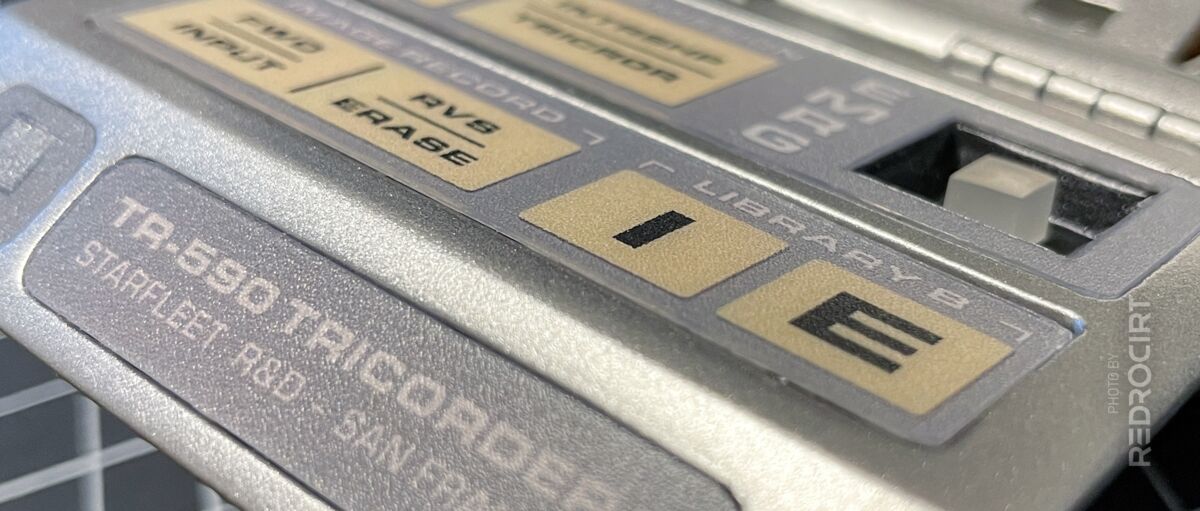
Labels for the flap/door
Section titled Labels for the flap/doorAfter many test prints and material selection, I finally prepared the stickers for the flap. I used tweezers with rounded tips to firmly attach the transparent adhesive film to the inkjet label and plastic cover and to rub out the small air bubbles that were visible before. Then I cut the stickers with a cutting ruler, cutting knife and scissors and finally glued them to the recessed touch button areas of the flap.
Note: Do not rub out the air bubbles on the front side as this will damage the PP. Rub only on the back side.
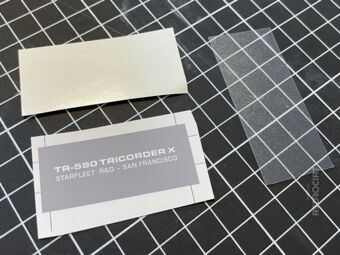
Sticker material for the nameplate 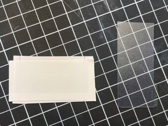
Transparent adhesive film onto print 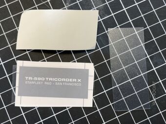
Removed the protective film 
PP sheet with anti-reflex surface 
PP placed on the adhesive film 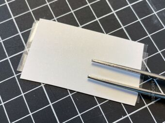
Rub out air bubbles from the back 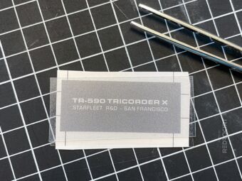
Front view without air bubbles 
Cut out shape with cutter/ruler 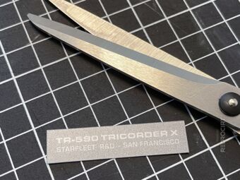
Rounding the edges with scissors 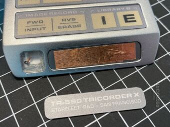
Cut in shape until it fits 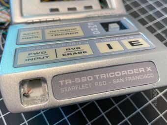
Remove protective film on the back 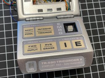
Stick the labels in place


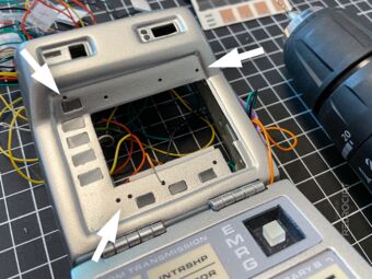
Preparing the touch pads in the main shell
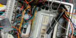
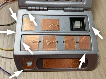
Section titled Preparing the touch pads in the main shellBefore I could apply the large UI sticker to the main shell, I had to drill holes for the wires and add the self-adhesive copper foil as conductive electrodes for the touchpads.
As you can see in the pictures below, I had also glued frosted/milky acrylic rectangles into the GEO-MET-BIO and PWR LED cutouts to serve as a light diffuser for the NeoPixels that will be placed behind them.
Drilled holes for the wires 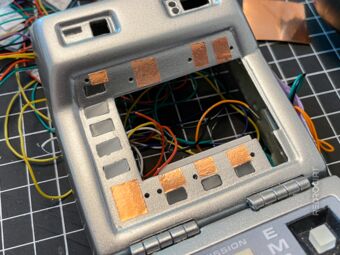
Added copper tape 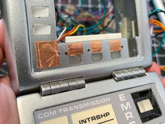
Stranded wires through the holes 
Fixed the wires with copper tape 
Wires exit below the reed switch 
Wires exit above the LED cutouts


Label for the main body
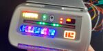
Section titled Label for the main bodyThis was (and still is) tricky. The user interface sticker for the main body is a mixture of capacitive touch keys, LED cutouts and a large cutout for the screen. I experimented with multiple sticker layers and reworked this sticker several times.
In the first picture below, you can see most of the material I used for this sticker:
- A) Transparent, double-sided adhesive foil (you can only see the protective film).
- B) A black shape with cutouts for the touch pads, printed on inkjet label paper. This layer will help to make the sticker opaque to prevent LED light shining through the sticker (reduce light bleeding).
- C) The interface graphic, also printed on inkjet label paper with photo quality.
- D) The squares from shape B, printed separately on label paper. This serves only as a cutting guide to cut the copper tape to the correct size.
- E) Self-adhesive copper tape as conductive electrodes for the touch pads.
- F) A sheet of PP plastic with anti-reflex coat for the special surface texture.
- G) Not in the picture: I also applied self-adhesive frosted glass film (that I had already used for the scanner front) to the LED cutouts to make the LED areas look silver when the LEDs are turned off.
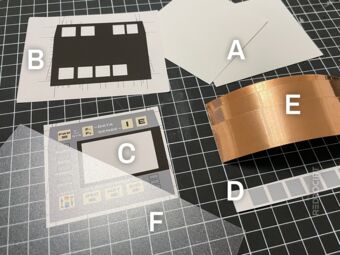
Material used for the sticker 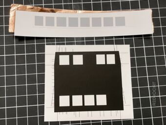
Cut out the squares 
Copper foil into the cutouts 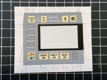
Stick UI label onto the black print 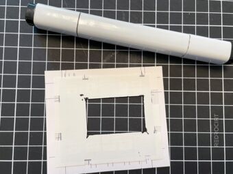
Cut out the display area... 
Painted edges with black marker 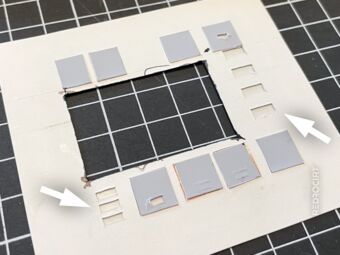
Cut out the LED rectangles 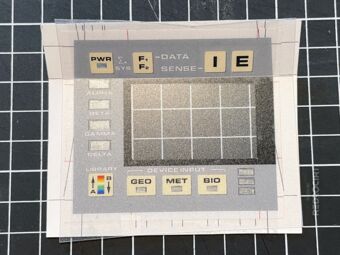
Add transparent plastic membrane 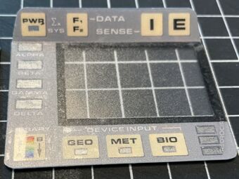
Cut contour and round corners 
Frosted glas film into LED cutouts 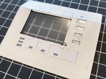
Rub out air bubbles from the back 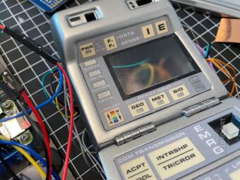
Stick the label in place


There may be some steps missing in this series of images. As mentioned above, I have revised this sticker several times and this is not the final version. I still have problems with the capacitive touchpads under this sticker, they sometimes do not respond. But overall, I'm happy with the look and feel.
The PP plastic cover, which I like for its textured surface, can be problematic for the TFT display underneath. The screen should be in direct contact with the PP cover to keep the screen content sharp and legible. Unfortunately, I have a small air gap between the TFT and PP cover, so the display looks a bit blurry.
I also tried cutting out the screen area from the PP cover, but it looked really ugly. In the TV series, the TR-590 user interface of the main body is flat with an integrated display. Since my replica only plays simple animations and has no real sensor functions, I can live with a slighly blurry screen for now.