Note: This is no general instruction, it is just a write up for my personal project. If you need help installing Raspberry Pi OS, please check out the official documentation and/or forums. Some content on this page may be outdated and may not work with the current Raspberry OS.
A fresh start with a new Raspberry Pi OS
Section titled A fresh start with a new Raspberry Pi OSOn Dec. 4th, 2020 there was a new release of Raspberry Pi OS with some fundamental changes, e.g. with sound processing. As my last larger script changes were about two months ago, I thought it's wise to rebuild the SD card with the operating system and thus have all software components up to date.
On this page I have documented the installation process in detail, mainly as a personal reminder of the single steps. These instructions were valid for the state of my test circuit in December 2020 and might be outdatet now.
Contents
- Backup, format, new installation
- Initial setup – basic settings
- More settings and copied data
- Disabled screensaver
- Turned off LEDs, changed editor settings
- Installed LiPoPi for battery power supply
- Installed PiTFT for the TFT display
- Enable interfaces and install Blinka
- Installed driver for touch sensors
- Installed Python-VLC
- USB sound card as default audio device
- Installed more Python libraries
- LED function tests
- Added settings for the reed switches
1) Backup, format, new installation
Section titled 1) Backup, format, new installation- SFTP: Copied my script folders lipopi, pitft and tricorder onto my computer
- SFTP: Also copied config.txt from Raspi's boot folder onto my computer
- Switched micro SD card from Raspi to my computer's SD card reader slot
- Backup: Made a full clone copy of the micro SD card with Win32 Disk Imager
- Format: Used SC Card Formatter to format the micro SD card (all data erased)
- Downloaded, installed and started Raspberry Pi Imager for Windows (version 1.5)
- Installed the current version of Raspberry Pi OS (32bit) onto the micro SD card
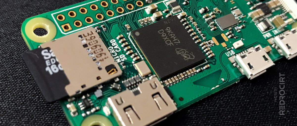
- Inserted micro SD card in a new Raspi Zero W, connected keyboard, mouse and monitor
2) Initial setup – basic settings
Section titled 2) Initial setup – basic settings- Powered up Raspberry Pi (SD card gets reformatted/initialized on first boot)
- Changed/confirmed localisation settings (country, language, keyboard layout)
- Set a passwort for the pi user account
- Confirmed monitor resolution settings
- Entered password for WLAN connection
- Loaded and installed updates (runs automatically after initial setup)
- Rebooted
3) More settings and copied data
Section titled 3) More settings and copied data- Activated SSH port in the Raspberry Pi Configuration
- Connected my computer with SFTP to Raspberry Pi
- Copied my script folders lipopi, pitft and tricorder back onto Raspi
- Started console LXTerminal and made another update with these commands:
sudo apt update -y
sudo apt-get update -y
sudo apt-get upgrade -y- Rebooted once again
- Connected Bluetooth keyboard/trackpad, disconnected USB mouse/keyboard
4) Disabled screensaver
Section titled 4) Disabled screensaverBy default Raspberry Pi turns off the screen after a couple of minutes inactivity. That is quite annoying when you use SSH to make changes, as well as when animations should run in a loop without interruption. I couldn't find screensaver settings on Raspi, so I searched for other options and found the app XScreensaver, which allows to disable the screensaver.
Note: XScreensaver should be installed before adding the small TFT screen, because the settings window of XScreensaver doesn't adapt or fit on the low resolution with 320×240 pixels. You need a larger monitor/resolution to use XScreensaver and disable the screensaver.
- Installed XScreensaver:
sudo apt install xscreensaver- Rebooted once again
- Then there was a new entry in Raspi's main menu > Settings > Screensaver
- Started the app Screensaver
- At mode selected Disable screensaver. The setting was saved by closing the window.
5) Turned off LEDs, changed editor settings
Section titled 5) Turned off LEDs, changed editor settingsIn my test circuit I have connected the LED TLC5947 breakout board's "enabled/OE" pin to Raspi GPIO6 already. By default the GPIO signal is low, so all LEDs will light up bright when the power is turned on.
To turn them off during Raspi's booting sequence I have to change the default GPIO signal to high. This is done in config.txt, but editing this file requires root privileges:
- On Raspi: Started console LXTerminal
- Used this command to run the file manager with root privileges:
sudo pcmanfm- The warning "x-terminal-emulator has very limited support..." can be ignored
- File manager started with root privileges
- In folders tree (left side) clicked on boot folder
- Right clicked on file config.txt, then in context menu clicked on Geany (code editor)
- At the beginning of the file I added this code:
# Switch off LED during boot sequence: set GPIO 6 HIGH
# op = output, dh = drive high for outputs
gpio=6=op,dh- Save file
At this stage I also changed the view settings of Geany to fit better on the small TFT screen:
- Menu View > untick Show Message Window (bottom window will be hidden)
- Menu View > untick Show Sidebar (left window will be hidden)
This way only the code area stays visible, that's enough for editing on the little TFT screen.
- Close Geany (code editor)
- Close File Manager
- Close LXTerminal (console)
- Reboot
6) Installed LiPoPi for battery power supply
Section titled 6) Installed LiPoPi for battery power supplyBattery power supply in my test curcuit is managed with the PowerBoost 1000C module. Before I can use the new formatted SD card in my test circuit, I have to install the LiPoPi scripts. Otherwise the Raspi wouldn't boot in my test circuit and turn off immediately.
I already copied the lipopi script folder onto the new SD card, but before installation some system settings needed to be changed.
- Started LXTerminal (console) and then entered:
sudo raspi-config- Used arrow keys to go to 3 Interfacing Options, confirmed with ENTER key
- Used arrow keys to go to P6 Serial Port, confirmed with ENTER key
- Question "Would you like a login shell to be accessible over serial?": Selected NO, confirmed with ENTER key. This should disable console output on the serial interface.
- Question "Would you like the serial port hardware to be enabled?": Selected YES, confirmed with ENTER key
- Confirmed changes once again with OK
- Back in the settings overview: Used tabulator key to jump to the bottom menu, selected FINISH and confirmed with ENTER key
- Question "Would you like to reboot now?": Selected YES, confirmed with ENTER key
- Reboot
Now I continued with the files in my lipopi folder:
- Started File Manager
- Selected folder /home/pi/
lipopi/ - Right clicked on file lipopi.py and selected file properties in the context menu
- Tab Permissions: Selected Everybody at Change content and Execute
- Confirmed with OK
- Created new sub folder /home/
pi/ lipopy/ log/ - Created new empty file lipopi.log in /home/
pi/ lipopy/ log/ - Started LXTerminal (console), changed to lipopi folder:
cd lipopi- Copied the lipopi "service" file in the system folder:
(Note: don't forget the dot at the end of the line)
sudo cp lipopi.service /etc/systemd/system/.- Enabled and started the service:
sudo systemctl enable lipopi.service
sudo systemctl start lipopi.service- Raspi was shutting down as expected, as there was no PowerBoost/LiPoPi signal yet
- Removed the micro SD card from the new Raspi and inserted it into the old Raspi within my test circuit (with connected PowerBoost module and LiPoPi circuit/connections)
7) Installed PiTFT for the TFT display
Section titled 7) Installed PiTFT for the TFT displayNext I installed the drivers for the TFT display. At my last setup I already made some changes in Adafruits PiTFT script, but in the meantime Adafruit had released an updated version on Github, so I decided to download their files again and compare them with my files.
To copy the Github files onto my Raspi I followed Adafruit's instruction for the 1.3'' 240x240 module. That's a different screen than mine, but it uses the same ST7789 driver.
- On my computer: Used Putty to connect to the Raspi via SSH (default host name raspberrypi, User pi and the password I set before)
- In the console I entered these commands (line by line, each line confirmed with ENTER key):
cd ~
sudo pip3 install --upgrade adafruit-python-shell click==7.0
sudo apt-get install -y git
git clone https://github.com/adafruit/Raspberry-Pi-Installer-Scripts.git- Then I compared the new version of adafruit-pitft.sh with my old version. The differences were minimal, so I decided to try it with Adafruit's newer version of this file.
- BUT I made a change in /overlays/
st7789v_240x320-overlay.dts :
I'm using SPI1 for the LEDs controll so I commented out the SPI1 block in this file:
fragment@0 {
  target = <&spi0>;
  __overlay__ {
    status = "okay";
    spidev@0{
      status = "disabled";
    };
/*
    spidev@1{
      status = "disabled";
    };
*/
  };
};- And further down in this file I changed spi-max-frequency from 32000000 to 40000000 (in my last tests it always worked with the higher frequency)
- Then I saved te changes and closed the file /overlays/
st7789v_ 240x320- overlay.dts - Renamed my old folder pitft to pitft_old
- Renamed the new folder Raspberry-
Pi- to pitftInstaller- Scripts - Deleted everything in this folder except the files adafruit-pitft.py and adafruit-pitft.sh and the sub folders overlays and st7789_module
- Then back to the Putty SSH console: For the final PiTFT installation I modified the install command for my display type, to have a 270° rotation and to use fbcp install mode to mirrow the HDMI signal to the TFT display:
cd pitft
sudo python3 adafruit-pitft.py --display=st7789_240x320 --rotation=270 --install-type=fbcp- The script then runed automatically and installed the display overlay and the fbcp drivers
- At the end I confirmed the question "Rebbot now" with y (= yes) and ENTER key
- After reboot the TFT display worked and showed Raspi's desktop (HDMI mirrow)
- Not related to PiTFT, but was detected after installation: Because the micro SD card is now placed in a different Raspi (in my test circuit) the Bluetooth connection to my wireless keyboard with trackpack was lost (probably due to a different Bluetooth ID of the Raspi). I had to temporarily remove the USB sound card in my test circuit and connect a USB keyboard to manually reset the Bluetooth connection.
8) Enable interfaces and install Blinka
Section titled 8) Enable interfaces and install BlinkaSome interfaces need to be activated before installing the drivers for LED and capacitive touch.
According to this instruction you should first update Python and set Python3 as default.
EDIT: This is not necessary. Setuptools were already installed and Python3 was default.
sudo pip3 install --upgrade setuptools
sudo apt-get install -y python3 git python3-pip
sudo update-alternatives --install /usr/bin/python python $(which python2) 1
sudo update-alternatives --install /usr/bin/python python $(which python3) 2
sudo update-alternatives --config python
Enabled I2C interface for touch sensors
Section titled Enabled I2C interface for touch sensorsThe capacitive touch module MPR121 is connected via I2C with the Raspi.
Instructions from Adafruit to enable I2C
- First installed helpers:
EDIT: This step is not necessary, both was already installed
sudo apt-get install -y python-smbus
sudo apt-get install -y i2c-tools- Then connected via Putty (SSH) and enabled the interface. Command to open configuration:
sudo raspi-config- Used arrow keys to go to 3 Interfacing Options, confirmed with ENTER key
- Used arrow keys to go to P5 I2C, confirmed with ENTER key
- Question "Would you like the ARM I2C interface to be enabled?": Selected YES, confirmed with ENTER key
- Confirmed changes once again with OK
- Back in the settings overview: Used tabulator key to jump to the bottom menu, selected FINISH and confirmed with ENTER key
- Question "Would you like to reboot now?": Selected YES, confirmed with ENTER key
- Reboot
Since the touch sensors are already connected, you can check whether they are recognized after the reboot. To do this, I connect again via Putty/SSH and entered the following command in the console:
sudo i2cdetect -y 1The two MPR121 modules should be displayed under the addresses defined with the ADDR PIN connections, i.e. 0x5B for the touch buttons in the upper shell and 0x5C for the touch buttons in the lower hinged lid:
.    0  1  2  3  4  5  6  7  8  9  a  b  c  d  e  f
00: -- -- -- -- -- -- -- -- -- -- -- -- -- -- -- --
10: -- -- -- -- -- -- -- -- -- -- -- -- -- -- -- --
20: -- -- -- -- -- -- -- -- -- -- -- -- -- -- -- --
30: -- -- -- -- -- -- -- -- -- -- -- -- -- -- -- --
40: -- -- -- -- -- -- -- -- -- -- -- -- -- -- -- --
50: -- -- -- -- -- -- -- -- -- -- -- 5b 5c -- -- --
60: -- -- -- -- -- -- -- -- -- -- -- -- -- -- -- --
70: -- -- -- -- -- -- -- -- -- -- -- -- -- -- -- --
Activated second SPI interface
Section titled Activated second SPI interfaceRaspberry Pi Zero has two SPI "channels":
- I'm using the first channel SPI0 for the TFT display (already activated and drivers installed)
- I'm using the second channel SPI1 for the LED drivers (TLC5947 and Dotstar Matrix)
Before activating the second channel I checked if SPI0 is detected correctly:
ls -l /dev/spidev*
The first channel SPI0 was detected as expected. To enable the second SPI channel I had to edit the /boot/
sudo pcmanfm- The warning "x-terminal-emulator has very limited support..." can be ignored
- File manager started with root privileges
- In folders tree (left side) clicked on boot folder
- Right clicked on file config.txt, then in context menu clicked on Geany (code editor)
- At the end of the file I added this:
dtoverlay=spi1-3cs- File > Save
- File > Quit
- Closed all windows and rebooted Raspi
- Then connected again via Putty/SSH and made a new SPI detection test:
ls /dev/spi*
That looked better, all SPI channels got detected now.
Installed Blinka library
Section titled Installed Blinka libraryAdafruit's Blinka library is used as interface to controll LEDs/Dotstars/Neopixels.
- Entered command to install Blinka in Putty/SSH console:
pip3 install adafruit-blinka- And rebooted again
sudo reboot now9) Installed driver for touch sensors
Section titled 9) Installed driver for touch sensorsNext I could install the MPR121 library for the capacitive touch modules:
sudo pip3 install adafruit-circuitpython-mpr121From my last setup I already had a script to test the touch sensors independent of the other modules. This script was designed to test the functionality of one touch module only. In my test circuit I now had two touch modules installed, but I wanted to give it a try anyways. To do so I first had to make the script executeable:
- Connected to Raspi via SFTP
- Changed to folder /home/
pi/ tricorder/ test/ - Right clicked on file test-touch.py and changed permissions to 755
- Then opened Putty/SSH console and called the script:
cd tricorder
cd test
sudo ./test-touch.py
Of course it didn't work immediately. In the test script I used MPG123 media player, so I had to install this for the test:
sudo apt-get install mpg123And now I had some trouble: During MPG123 installation Raspi suddenly shut down without any warning. So I rebooted and tried it again. This time MPG123 got installed. I rebooted once again and now the TFT display didn't work anymore. So I run the PiTFT installer script once again and rebooted another time. I made some changes to my touch sensor test script and it also finaly worked as expected.
10) Installed Python-VLC
Section titled 10) Installed Python-VLCIn an older release of Raspberry Pi OS the VLC media player got improved with hardware acceleration, so I wanted to use VLC for the video playback. To controll VLC via Python there is a interface library available:
sudo pip3 install python-vlc11) USB sound card as default audio device
Section titled 11) USB sound card as default audio deviceThe GPIOs for I2S are already blocked in my setup. I'm using an external USB sound card instead. In the older Raspberry Pi OS version the USB sound card had to be set up as the default output device for audio. This seems to be obsolete now as they switched to use the PulseAudio sound server instead of ALSA and my USB sound card is working for system sounds without any system modifications.
BUT of course it didn't work when I tested my script. There was no audio output to hear. And also no error message. I figured out that I still need some modifications to use the USB sound card with PyGame.
I first made some functionallity testing:
- To check if the USB device is detected, enter this command in the console:
lsusb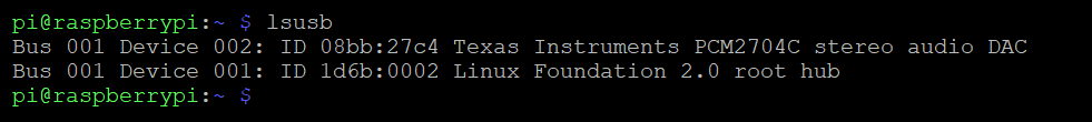
- To get the USB card numers as a compact list:
aplay -l- Or more detailed:
aplay -LTo get the USB sound card working with PyGame I had to change the default audio device for the root user environment (I have to call my scripts with sudo because of the Neopixels). I found some helpful instructions in the Raspi forum.
- First I made a backup of the ALSA configuration file:
cd /usr/share/alsa
sudo cp alsa.conf alsa.conf.orig- Then the file /usr/
share/ alsa/ alsa.conf had to be edited: In two lines the sound card had to be changed from 0 to 1 (1=USB since the latest Raspberry Pi OS, before no. 2 was the USB sound card). I made the changes directy via console with the nano editor:
sudo nano alsa.conf- In the following two lines the number "0" had to be replaced with "1":
defaults.ctl.card 0
defaults.pcm.card 0- Saved the file
- Quit the editor
- Made a simple audio test via console:
cd ~
cd tricorder
cd audio
sudo aplay tricorder.wav
That worked fine. I also made a PyGame sound test with my script and it also worked.
12) Installed more Python libraries
Section titled 12) Installed more Python libraries- For the 24-channel LED breakout (TLC5947):
sudo pip3 install adafruit-circuitpython-tlc5947- Dotstar library for the mini LED matrix:
sudo pip3 install adafruit-circuitpython-dotstar- Neopixel library for the RGBW-LEDs:
sudo pip3 install adafruit-circuitpython-neopixel- Note to myself: PyGame is already installed (comes with Raspberry Pi OS)
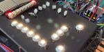
13) LED function tests
Section titled 13) LED function testsNeopixels
Section titled NeopixelsWith some adjustments in my test script all Neopixels lighted up and could be controlled individually.
But some Neopixels flickered and showed wrong colors. I guess I damaged them during soldering (too hot). Another problem could be the voltage of the data signal line: Raspi's GPIO output is 3.3V, Neopixels expect 5V when powered with 5V. This is also explained in this article about glitchy Neopixels.
I'll replace the flickering Neopixels and make a new test series...
Dotstar matrix and TLC5947 LEDs
Section titled Dotstar matrix and TLC5947 LEDsA first quick test was successful. But I have to change my test script because I had changed the LED pins of the TLC5947 breakout in my circuit. I'm also thinking about replacing the last red "LED-Sequins" with Neopixels...
New day, new tests
Section titled New day, new testsI replaced the malfunctioning Neopixels in my test circuit and made a new running test. Now all Neopixels are working correctly, so I'm quite sure I damaged the older ones when soldering too long or too hot.
After a few changes in my scripts I also could recover the old blinking sequences and adapt them to my new LED pin connections and changed Neopixel order in my test circuit.
Adafruit recommends to increase the data signal voltage of the Raspberry Pi for the Neopixels with a level shifter from 3.3V to 5V. I ordered a 74AHCT125 chip for testing and might include this chip in my test circuit.
EDIT: I received the 74AHCT125 level shifter chips, but unfortunatelly I didn't check the size during the order and now I have some SMD parts with very tiny pins. I'm not sure if I can solder this and postpone the tests with this level shifter.
14) Added settings for the reed switches
Section titled 14) Added settings for the reed switchesIn the technical diagram for my test circuit I had already added the two magnetic reed switches that detect when the Tricorder gets opened or closed, so I can play the well-known "ratchet" sound effect. The Raspi settings for these reed switches had to be done again:
- Edited the file /boot/
config.txt and added the used GPIOs as input with pull down:
# Reed switches
# GPIO 27 = Tricorder opened/closed
# GPIO 17 = Closing ratchet sound
gpio=27=ip,pd
gpio=17=ip,pd- Here's an example for using the reed switches with Python