Note: This article describes my first attempts. While I continued to use the TLC5947 breakout board, I later changed the setup and also added SK6812RGBW “Pixels” with integrated driver chips.
Preparing the RGB LEDs
Section titled Preparing the RGB LEDsI've ordered diffused rectangular 2.5 mm × 5 mm RGB LEDs. To prevent light bleed, I carefully glued 0.5 mm black opaque PVC to all sides, as well as to the bottom around the pins.
The RGB LEDs have four pins of different lenghts. I looked in the data sheet for the polarity and pin colors. Usually red colored wire is used for the anode (+), but in this case I thought it would be better to use colored wires for the cathodes (-) to know which pin is for which color because I need to shorten the pins.
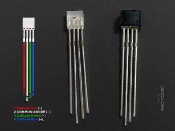
Polarity according to data sheet 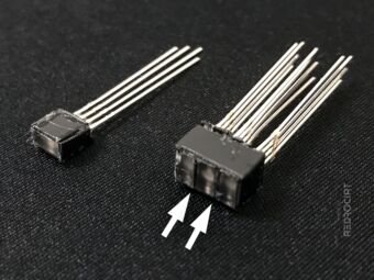
Opaque PVC between/around LEDs 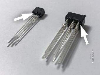
Prevent bottom light bleed 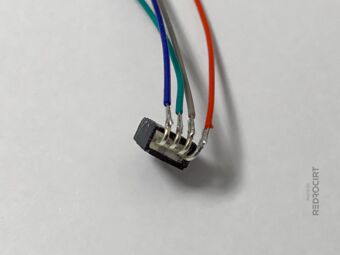
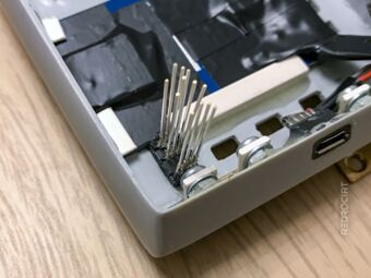
Pins trimmed and bended 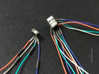
Adding heat shrink tubing 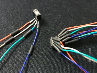
Wire colors = channels, not polarity


Find a good position for the LED board
Section titled Find a good position for the LED boardI wanted to place the TLC5947 board direcly above the TFT display board and get the boards as flat as possible on top of each other. Both boards have low height electronic components on one side. I covered all the metallic parts and contacts on the TFT board with electrical insulating tape, and tried to find a good position for the TLC5947 board where the protruding components would not overlap directly.
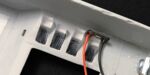
Fitting test for the scan LED row 
Front view of the scan LED row 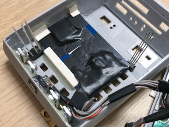
Insulating tape covering contacts 
Positioning the breakout board 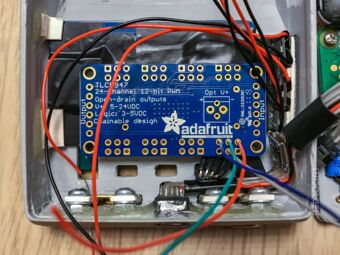
Wiring test with the first RGB LED 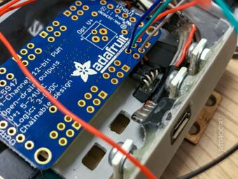
Pins and wires tightly bent


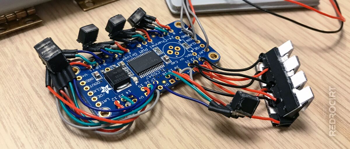
Connecting RGB LEDs to TLC5947 board
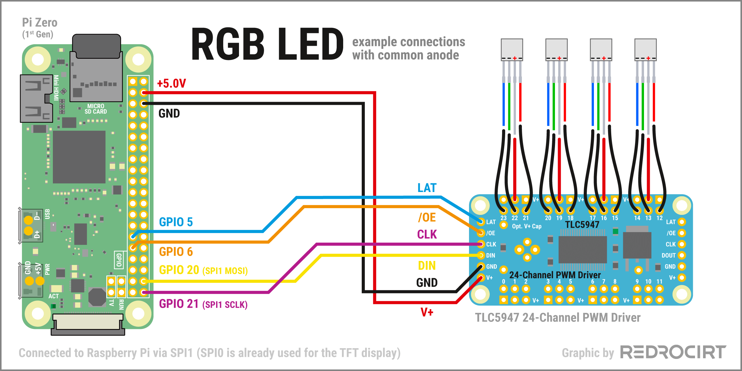
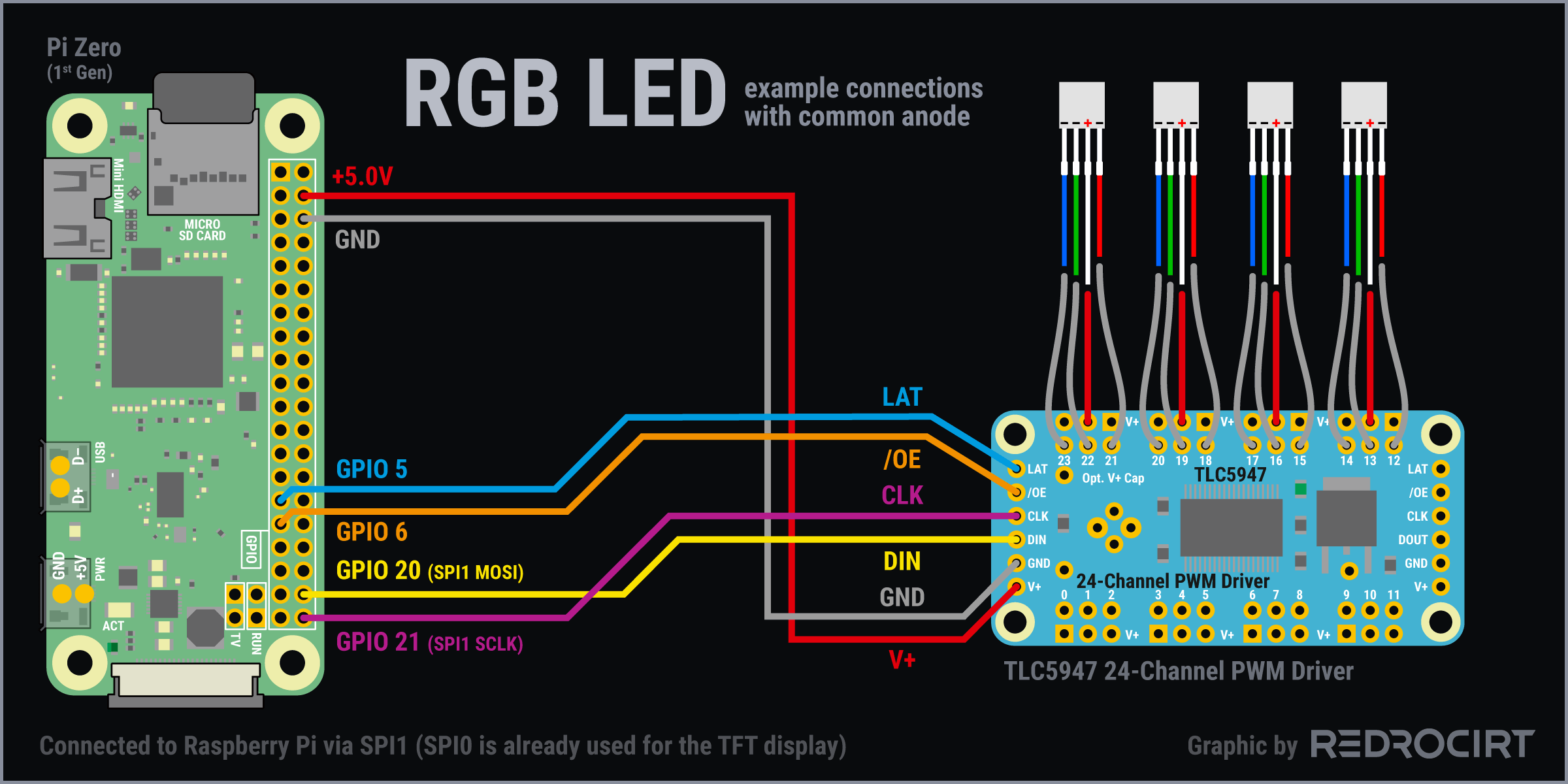
Section titled Connecting RGB LEDs to TLC5947 boardThe TLC5947 breakout board can control 24 channels of 12-bit PWM output. RGB LEDs use three channels each (red, green, blue), so a maximum of 8 independent RGB LEDs is possible. Since I also wanted to connect single-color LEDs, I planned to use fewer RGB LEDs and omit some colors.
The RGB LEDs I have a common anode (+). The diagram below shows the basic wiring for connecting the LEDs with the TLC5947 breakout board. This is only an example. I didn't always connect the color channels in the same order because I could easily define the pin assignment in the Python script. I soldered the wires in the order they were closest to the pin holes to keep the wires as short as possible.
Using SPI1 for the TLC5947 breakout board
Section titled Using SPI1 for the TLC5947 breakout boardThe breakout is connected to Raspi via SPI (Serial Peripheral Interface). Raspberry Pi Zero (version 1) has two SPI controllers, SPI0 with two hardware chip selects (CS pins) and SPI1 with three hardware chip selects. SPI0 is already used for the TFT display, so I wanted to use SPI1 for the LEDs instead.
- Connected Raspi's +5.0V GPIO with V+ on the TLC5947 breakout, as well as GND. Note: I later connected V+ directly to PowerBoost's +5v output to prevent damaging Raspi's GPIO (because 24 LEDs á 60 mA max. = 1.440 mA max. = too much for Raspi's GPIO, as far as I understand it).
- GPIO 21 is Raspi's clock signal for SPI1 (“SCLK”). Connected it with CLK on the breakout.
- GPIO 20 is Raspi's data output for SPI1 (“MOSI”). Connected it with DIN (“data in”).
- The TLC5947 uses a third SPI line "latch", which can be connected to any unused GPIO. You just have to change the pin number in the Python script. I connected LAT to GPIO 5
- The /OE pin on the TLC5947 breakout is optional and can be raised to quickly turn off all LEDs (it is pulled low by default). /OE can be connected to any unused GPIO, I connected it to GPIO6.
Solder everything together
Section titled Solder everything togetherFinally, I soldered all the connections. At this first assembly I used
- 4 channels for the Alpha-to-Delta lights (green “Sequin” LEDs)
- 9 channels for the GEO-MET-BIO button LEDs (3× RGB)
- 9 channels for the scan LED row (3× RGB)
- 2 channels (only green and red) for the Power LED
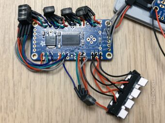
LEDs soldered to TLC5947 board 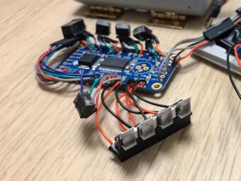
Alpha-to-Delta “Sequin” LEDs 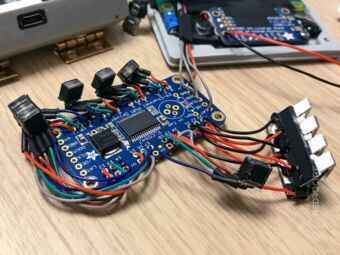
Wires kept as short as possible


The TR-590 has many more LEDs, and at that time I did't know how I was going to controll them. But anyway, before I could move on, I thought I'd better should start programming and testing to see if my setup would work in general...