Disclaimer: I am not an expert in electronics or programming. That's the way I did it, and that's not necessarily the correct way to do it.
I have revised the drawing of my test board schematic several times in the last weeks and integrated the new components. I added the USB sound card with the TPA2012 Audio Amp, the series connection of the TLC5947 LED board with the DotStar Matrix panels, and the NeoPixel stick. To maintain a compact form factor and make the parts more accessible, I rearranged all the parts.
Note: It's recommended to use a logic level shifter like 74AHCT125 to boost Raspi's 3.3V GPIO data signals to 5V for modules that are also connected directly to the 5V power line. I didn't use a logic level shifter, but I should have (it worked without, but not reliably). Use a logic level shifter!
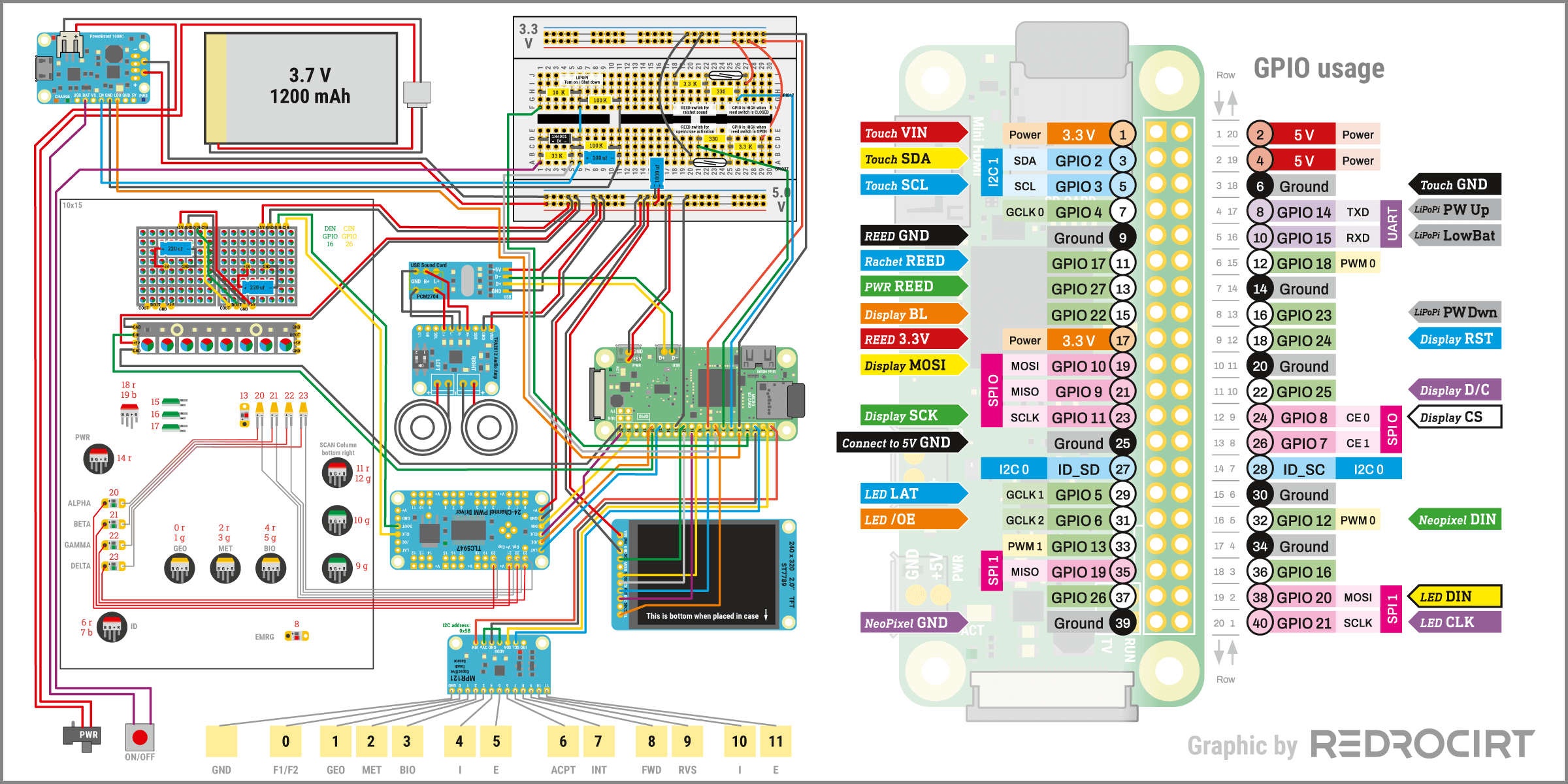
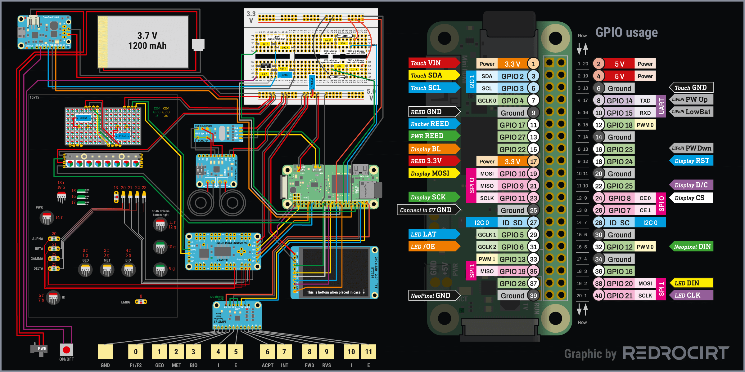
I also changed some of the LED connections on the TLC5947 and integrated the splitted 10 segment LED light bar graphs in series with the Alpha-to-Gamma lights. This setup will change again soon, as I will be replacing the Sequin LEDs and some of the rectangular RGB LEDs with NeoPixel Buttons as they become available. But for now, I was happy with the circuit and ended up taking apart my first test board and building a completely new test board:
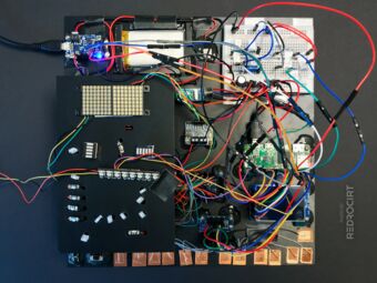
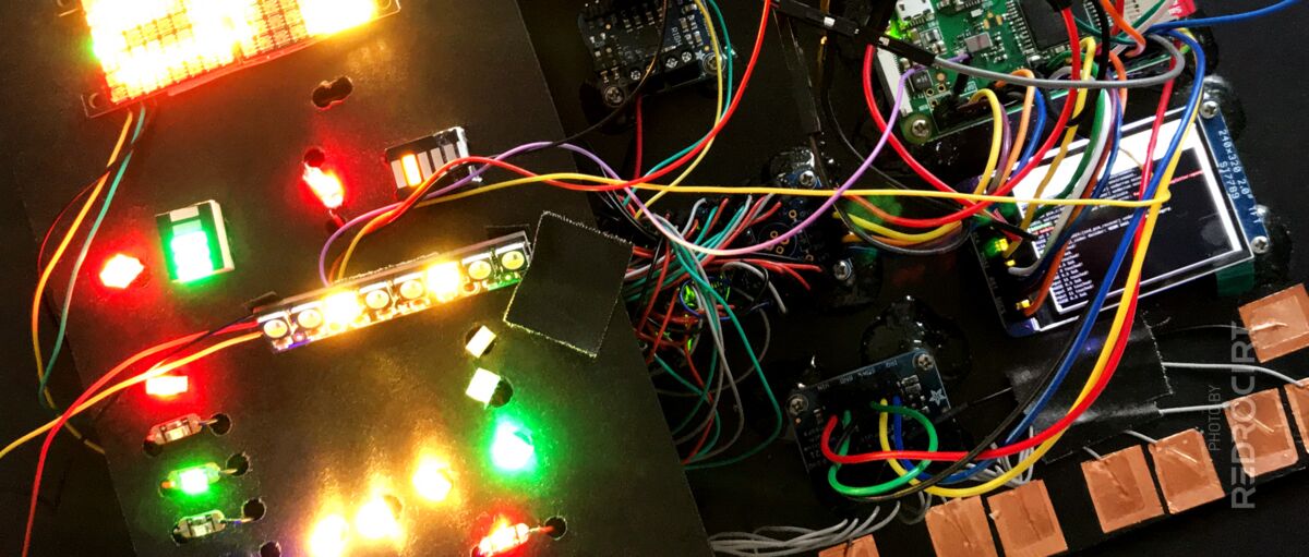
Top view of the test rig 
New LED arrangement 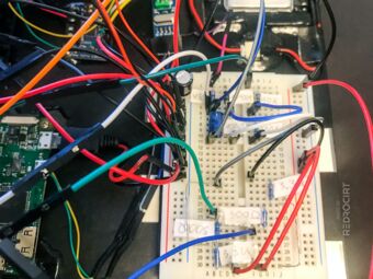
LiPoPi and reed switch circuits 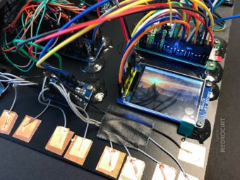
TFT screen and touch buttons 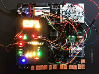
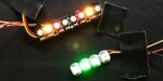
LED function test 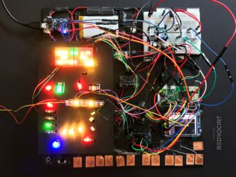
LED function test


And here it is in action:
Currently used components and connections
Section titled Currently used components and connections- 3.7V LiPo with 1200 mAh (I already noticed some power problems, might need a larger battery)
- PowerBoost 1000C is boosting 3,7V to 5V (and charging the LiPo via micro USB)
- Physical power switch to completely disconnect the battery from the PowerBoost
- LiPoPi circuit (left side of the breadboard) with a push button to power up or shut down the Raspi
- Raspberry Pi Zero (1st Gen.) with micro SD card
- USB sound card (PCM2704) connected to Raspi's USB test pins on the back
- TPA2012 Audio Amp connected to the headphone jack of the USB sound card
- One speaker connected to the TPA 2012 Audio Amp (later there will be 2 for stereo sound)
- One MPR121 12-channel capacitive touch module, connected via I2C
- ST7789 320x240 SPI TFT display, connected via SPI0
- TLC5947 24-Channel LED controller, connected via SPI1
- Different types of LEDs (Sequins, rectangular RGB and segmented bars) connected to TLC5947
- Two DotStar 8×8 matrix boards, connected in series to TLC5947 (via SPI1)
- One RGBW NeoPixel stick, connected via GPIO12 (PWM0) - will later be extended with more NeoPixels
- Because of the many LEDs used, I also added a 1000 uf capacitor to the 5V line
- Two reed switch circuits (right side of the breadboard) to detect the status of the door