Note: Some content on this page may be outdated and may not work with the current Raspberry OS.
In the last weeks I read a lot of tutorials about Raspberry Pi and Python, tried some test scripts and searched for other breakout boards. In retrospect, it wasn't a good idea to solder the first components together in advance to fit the shell. It became difficult to connect the Raspi to a large monitor and a USB keyboard, and I didn't yet know what other components I would add and what the circuits would look like....
Contents
Preparing a separate test setup for the electronics
Section titled Preparing a separate test setup for the electronicsI finally started drawing wiring diagrams with the components I wanted to use, and ordered more parts to make a separate test setup with a breadboard where I can more easily access or replace the breakout boards and change connections. I should have done that first, it's easier to see/know which GPIOs are already in use and how to connect all the power/ground paths etc. I didn't take photos of my test board at this stage, but the components were arranged similarly to the schematic below.
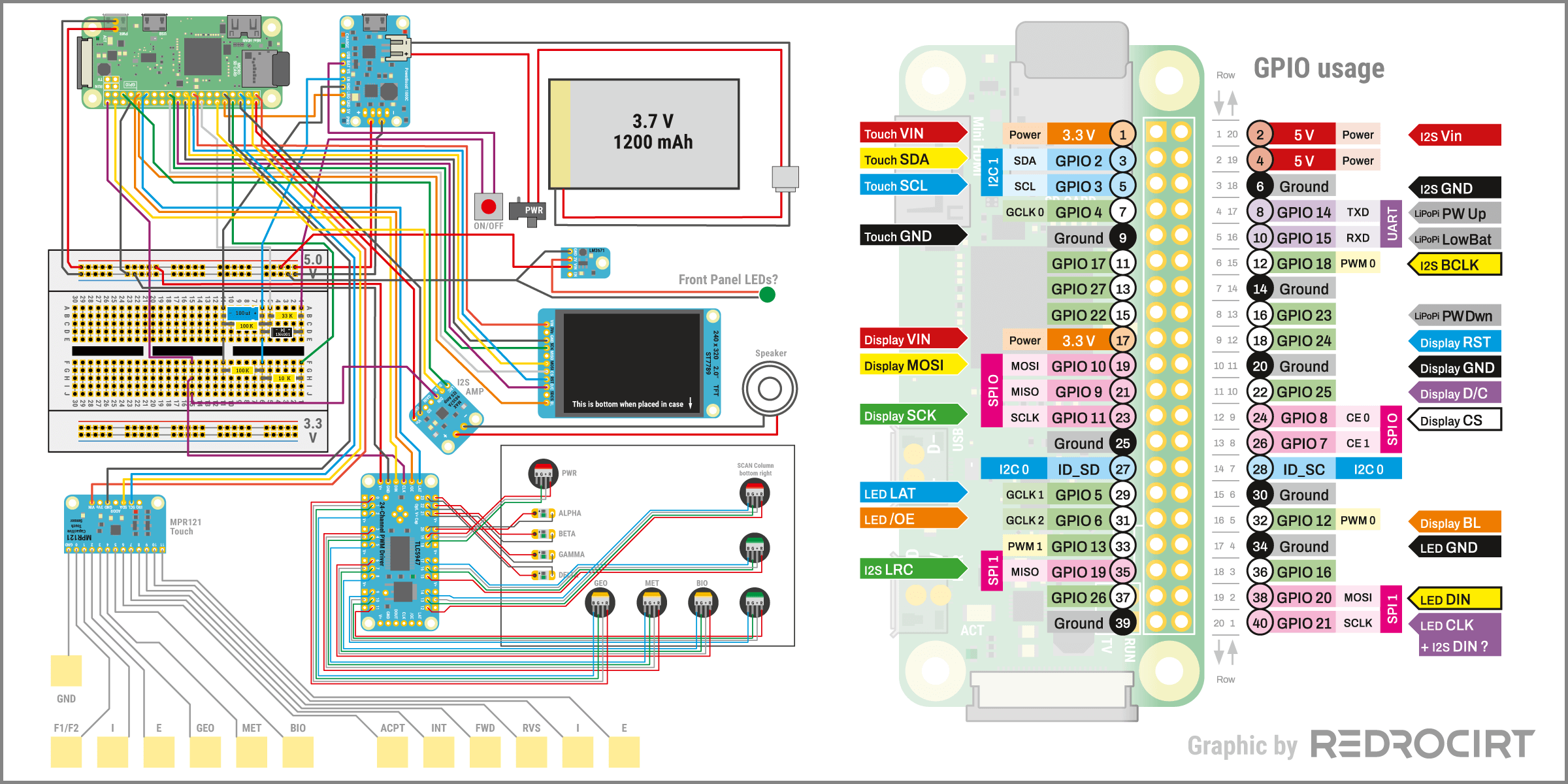
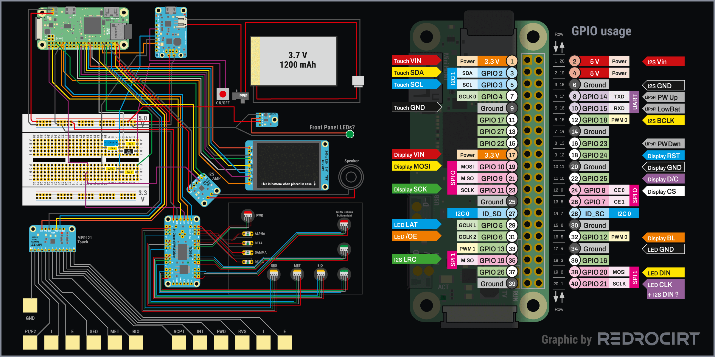
The website pinout.xyz is a great reference to the Raspberry Pi GPIO pins and interfaces.
Audio via I2S?
Section titled Audio via I2S?I wanted to add small speakers to my TR-590 so I could play the typical scanner sound and beeps when buttons get touched. “I2S” seemed to be the way to go, since the Raspberry Pi Zero doesn't have a 3.5mm audio jack. I ordered a MAX98357A 3W I2S amplifier breakout and different types of small speakers.
When I added the I2S breakout to my schematic, I noticed that I2S requires the same GPIOs that I already wanted to use with SPI1 to control the LEDs with the TLC5947 breakout. Probably I have to find another solution for the audio output. But first I continued with other things.
Adding a boot splash screen
Section titled Adding a boot splash screenDuring testing, I had to reboot the Raspberry Pi a lot, and I thought it would be nice to have a custom splash screen during the boot sequence. There are several ways to do this, and you can also get rid of the rainbow image if you want. I just created a custom graphic with 640×480 pixels, saved it as splash.png file and copied it onto the Raspi in the folder /usr/
Disable the screensaver
Section titled Disable the screensaverBy default Raspberry Pi turns off the screen after a couple of minutes inactivity. That is quite annoying when you use SSH to make changes, as well as when animations should run in a loop without interruption. I couldn't find screensaver settings on Raspi, so I searched for other options and found the app XScreensaver, which allows to disable the screensaver.
Note: XScreensaver should be installed before adding the small TFT screen, because the settings window of XScreensaver doesn't adapt or fit on the low resolution with 320×240 pixels. You need a larger monitor/resolution to use XScreensaver and disable the screensaver.
- Installed XScreensaver:
sudo apt install xscreensaver- Rebooted once again
- Then there was a new entry in Raspi's main menu > Settings > Screensaver
- Started the app Screensaver
- At “mode” selected “Disable screensaver”. The setting was saved by closing the window.
- (After that I installed the PiTFT helper display driver again)
Experimenting with video players
Section titled Experimenting with video playersI had prepared some test animations (MP4 at 25fps, 640×480px) and tried various code snippets I found online to play and control the videos with a Python script. I experimented with MPlayer, OMXPlayer and VLC (Python-VLC) but had some trouble with all of them. I will continue to research and test...
OMXPlayer example
Section titled OMXPlayer exampleomxplayer-wrapper is a project to control OMXPlayer from Python over dbus.
Note: OMXPlayer is deprecated, do not use it in newer projects.
# Install DBUS:
sudo apt-get update && sudo apt-get install -y libdbus-1{-3,-dev}
# Install OMXPlayer:
sudo apt-get install omxplayer
# Install OMXPlayer-wrapper:
sudo pip3 install omxplayer-wrapper
Python script: (this is just a test example)
#!/usr/bin/python3
#!/usr/bin/env python3

# Import libraries
from pathlib import Path # for declaring file paths
from time import sleep # for timing control
from omxplayer.player import OMXPlayer # for video player control

# Path to video file
VIDEO_PATH = Path('/home/pi/Videos/test.mp4')
# Initialization of the player without user interface, play in a loop
player = OMXPlayer(VIDEO_PATH, args=['--no-osd', '--loop'])
# Wait 30 seconds, then stop
sleep(30)
player.quit()
Testing the TLC5947 LED breakout
Section titled Testing the TLC5947 LED breakoutBefore I could write test code to control the LEDs with TLC5947, I had to install the drivers. This requires to first install the adafruit_blinka library.
Install adafruit_blinka
Section titled Install adafruit_blinkaTo install blinka, I followed the instructions here:
# Update Pi and Python:
sudo apt-get update
sudo apt-get upgrade
sudo apt-get install python3-pip
# Then install setuptools:
sudo pip3 install --upgrade setuptools
# The copy the Blinka installer files and run the script:
cd ~
sudo pip3 install --upgrade adafruit-python-shell
wget https://raw.githubusercontent.com/adafruit/Raspberry-Pi-Installer-Scripts/master/raspi-blinka.py
sudo python3 raspi-blinka.py
Enabling Second SPI
Section titled Enabling Second SPIAnd I added dtoverlay=spi1-3cs at the bottom of /boot/
Install TLC5947 drivers
Section titled Install TLC5947 driversPython Installation of TLC5947 is quite easy:
sudo pip3 install adafruit-circuitpython-tlc5947Test scripts for controlling the LEDs
Section titled Test scripts for controlling the LEDsI followed the examples and started working on custom functions and blink sequences. I won't post my full test scripts here because they were a mess and I changed my code several times. However, I would like to highlight two things:
Since I wanted to use SPI1 instead of SPI0, I had to change the GPIO declarations:
#!/usr/bin/python3
#!/usr/bin/env python3

# Import libraries
import board
import busio
import digitalio
import adafruit_tlc5947 # for 24 channel LED controll board

# LED initialisation: define GPIOs connected to TLC5947
# Using second SPI channels, because first ones are blocked by TFT display. More info:
# https://learn.adafruit.com/tlc5947-tlc59711-pwm-led-driver-breakout/python-circuitpython
SCK = board.SCK_1 # Second SLCK channel (GPIO 21 = LED SKL)
MOSI = board.MOSI_1 # Second MOSI channel (GPIO 20 = LED DIN)
LATCH = digitalio.DigitalInOut(board.D5) # GPIO 5 for LED LAT control
spi = busio.SPI(clock=SCK, MOSI=MOSI) # Initialize SPI bus
tlc5947 = adafruit_tlc5947.TLC5947(spi, LATCH) # Initialize TLC5947
And I wanted to be able to turn all the LEDs on or off with a simple command. In my test circuit I had connected the TLC5947 breakout board's /OE (enable) pin to Raspi GPIO6 already.
By default the GPIO signal is low, so all LEDs will light up bright when the power is turned on. To turn them off during Raspi's booting sequence I had to change the default GPIO signal to high. This is done in /boot/
# Switch off LED during boot sequence: set GPIO 6 HIGH
# op = output, dh = drive high for outputs
gpio=6=op,dh
In the Python script, the LEDs can be turned on or off altogether by changing the GPIO status:
# Import libraries
import RPi.GPIO as GPIO # for reading/setting GPIO signals
# [...]
# OE is connected to GPIO 6, signal high = LED off, signal low = LED on
ledoe = 6
GPIO.setmode(GPIO.BCM)
GPIO.setup(ledoe, GPIO.OUT)
GPIO.output(ledoe, GPIO.LOW) # Low = LEDs on
# [...]
# To switch all LEDs off: set signal high
GPIO.output(ledoe, GPIO.HIGH)
TFT display: Switching on or off the backlight
Section titled TFT display: Switching on or off the backlightIn my test circuit I had connected the display's BL (backlight) pin to Raspi's GPIO12 (PWM0). The brightness of the backlight can be controlled by changing the PWM output in the Python script. I wrote short functions for that:
# SPI display backlight control via GPIO 12
GPIO.setmode(GPIO.BCM)
GPIO.setup(12, GPIO.OUT)
backlight = GPIO.PWM(12, 50)  # channel=12 frequency=50Hz
backlight.start(0) # To start PWM; where dc is the duty cycle (0.0 <= dc <= 100.0)

def displayon():
  for dc in range(0, 101, 5):
    backlight.ChangeDutyCycle(dc)
    time.sleep(0.01)

def displayoff():
  for dc in range(100, -1, -5):
    backlight.ChangeDutyCycle(dc)
    time.sleep(0.01)

# Switch the display backlight on:
displayon()

# Wait 3 Seconds (or other code here)
sleep(3)

# Switch the display backlight off:
displayoff()

# Or switch it off immediately:
backlight.ChangeDutyCycle(100)
Note: I later changed the connections and used GPIO22 for the TFT backlight instead.