After replacing the rear cover, I could install the last electronics (see also part 1 and part 2).
Contents
Connecting the Raspberry Pi Zero
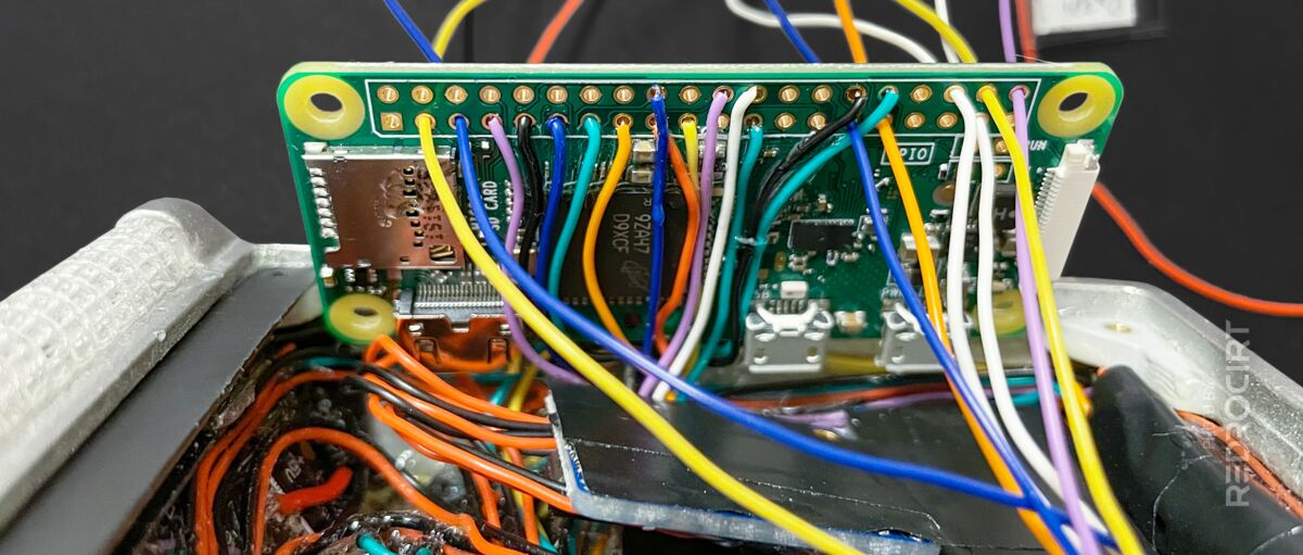
Section titled Connecting the Raspberry Pi ZeroI wanted the Raspberry Pi Zero to be detachable to be able to access the MicroSD card slot and USB jacks. The wires had to be a little longer for this to work, but I still tried to keep them as short as possible. The LiPo battery will be placed on top of RasPi's flat back side, so all wires run on the underside.
Assign the wires to the pins 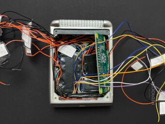
Longer wires (RasPi detachable) 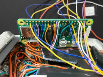
Connecting Raspberry Pi Zero


After soldering the wires to the RasPi according to my schematic, I noticed that some wires were now too short to lift the RasPi and reach the ports. So I unsoldered them again and extended them a bit (protecting the connections with heat shrink tubing) and soldered them on the RasPi again.
One more thingis worth mentioning here: I didn't solder the wires for the USB sound card directly onto the USB data ports on the Raspberry Pi. Instead I added jumper connectors in between to be able do disconnect the sound card and plug in other USB devices to RasPi's USB socket.
PowerBoost, LiPoPi and power switches
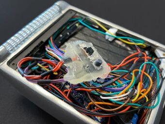
Section titled PowerBoost, LiPoPi and power switchesAll power wires were routed to the upper left corner, where I soldered them together and added an extra 1000µF capacitor to absorb voltage spikes. I connected the power lines to the PowerBoost module (transforming LiPo's 3.7V to 5V) and also added the LiPoPi circuit and main switches.

All power lines connected 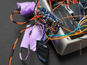
PowerBoost and LiPoPi 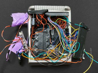
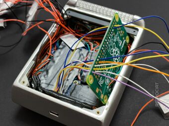
All electronics connected


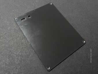
Preparing the rear lid
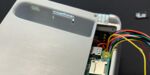
Section titled Preparing the rear lidNext, I drilled and filed holes for the power switches in the upper left corner of the lid plate. The rectangular hole is for the slide switch, which can be used to completely disconnect the LiPo battery. The other, round hole is for the push button to turn on or off the Raspberry Pi (LiPoPi circuit). Then I sanded the surface, sprayed with primer and filler, sanded again and sprayed with metallic silver and clear coat.
Holes for the power switches 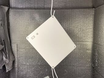
Spray painting primer and filler 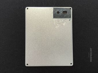
Inside of the lid, partly unpainted


Since I was painting anyway, I also touched up some minor damage to the paint on the main body. I had previously slipped with the soldering iron while soldering the cables to the Raspberry Pi.
Glue the switches on the lid
Section titled Glue the switches on the lidOn the inside of the lid, I had covered the area around the switch holes with tape before spray painting so that I could glue the switches in place and the glue would adhere better to the roughened acrylic surface. Unfortunately, the liquid adhesive got inside the switches and made them unusable.
I scraped off the dried glue and of course damaged the paint, so I had to spray paint the lid once again. I cut off the wires of the old switches, replaced them, and carefully tried gluing them to the lid again.
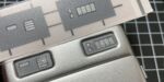
Detached, defective switches 
Cut off the defective switches 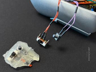
Solder new switches to the wires 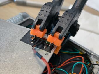
Clamp the switches in position 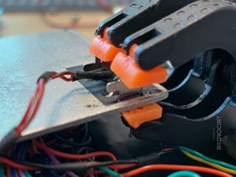
Carefully add epoxy glue dots 
Later carefully added more glue


Insert the LiPo battery
Section titled Insert the LiPo batteryDoes it fit? Well, kind of. Although I had increased the height, the lid bulges when the battery is inserted. It's not pretty, but I can (have to) live with it. If I ever build another Tricorder, I'll have to approach it differently. But at least I used only of-the-shelve breakout boards and electronic components for this Tricorder.
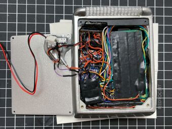
All components in place 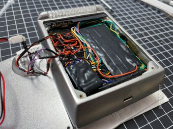
Tried to make it as flat as possible 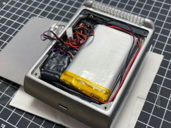
LiPo goes on top of RasPi 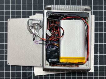
Top view with LiPo battery 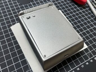
Rear view of the closed Tricorder 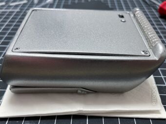
The LiPo bends the lid


I had painted the lid again to prevent light bleeding in the area of the power switches and to make the switches silver. With that, I was basically done with the assembly. Over the next few weeks, I focused on improving the software and added more LED flashing sequences.