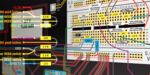
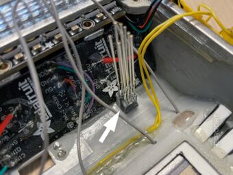
This looks like a mess... But everything has its place. And it works (at least so far).
Note: I have decided to glue many parts permanently into the case. I know this makes maintenance or replacement virtually impossible. If something goes wrong, I consider this build a failed prototype ;-)
Contents
- Installation of acrylic light guides
- Preparation of the rectangular LEDs
- Adding the screen and attaching speakers
- RGBW NeoPixels for the GEO-MET-BIO buttons
- Final installation of the USB socket
- RGBW NeoPixels for the Alpha-to-Delta lights
- RGBW NeoPixels for upper light positions
- Updated NeoPixel chain
Installation of acrylic light guides
Section titled Installation of acrylic light guidesAfter inserting my custom acrylic light guides for the Alpha-Delta flashing lights into the cutouts in the shell, I permanently fixed them with a drop of 2-component epoxy. To prevent sideways light bleed from the individual LEDs, I cut small triangles out of black opaque PVC and carefully glued them to the sides.
Light guides glued in position 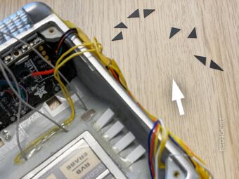
Cutting black triangles 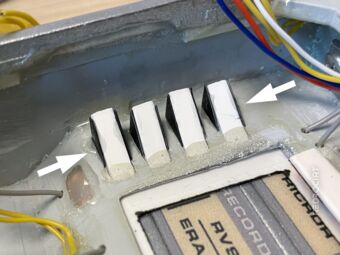
Triangles glued on the sides


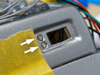
I had also cut 2 short pieces from a round acrylic rod with a diameter of 2 mm, sanded the upper and lower ends and glued them into the holes for the round LEDs on the upper right. From the outside it will look like two separate LEDs due to the separate acrylic rods that act as light guides. In fact, I will light both light guides with a single 5mm RGBW NeoPixel from the inside.
Round acrylic rod pieces 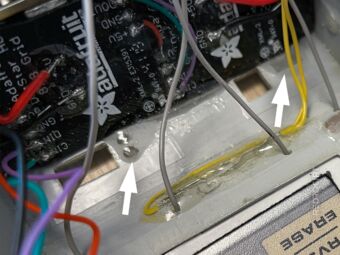
Light guides for the top LED row 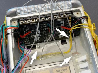
And a light guide for the power LED


On the other side of the top row of LEDs, I glued in another rectangle made of frosted acrylic glas as a light guide (hidden behind the yellow wires of the reed switch in the interior view pictures). And let's not forget the acrylic light guide for the power LED (last image above, above the Alpha-Delta light guides).
Preparation of the rectangular LEDs
Section titled Preparation of the rectangular LEDsSeveral rectangular, multi-colored RGB LEDs go into the larger openings of the shell. The rectangular LEDs that I ordered fit well in terms of format, but are only slightly diffuse. So I decided to glue on small blocks of milky/frosted acrylic glass here, too, to get an evenly illuminated surface. I also glued thin strips of black opaque PVC to all sides again to prevent lateral light bleeding as much as possible.
Fitting test with 2 rectangular LEDs 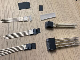
Attach frosted acrylic pieces 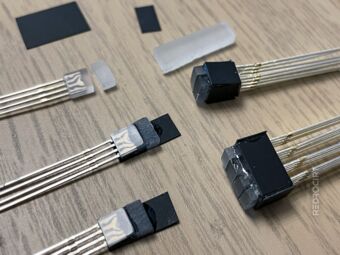
Black PCV to prevent light bleeding 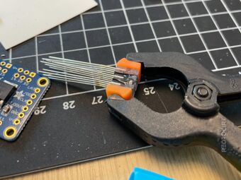
Glue LEDs together 
Add more black PVC 
With soldered and insulated wires


After the glue dried, I shortened the metal pins and soldered colored wires to them. I added heat shrink tubing for insulation and bent the pins to get a compact form factor.
Adding the screen and attaching speakers
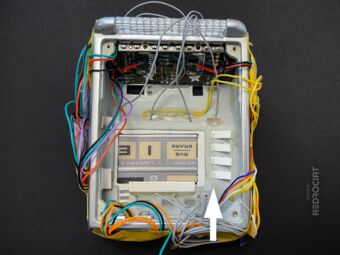
Section titled Adding the screen and attaching speakersAfter soldering colored wires to the screen, I slid the TFT display temporary into place. I used insulating tape to fix the screen's cables so that they were all aligned with the top of the board. This means I no longer have to run them along the side wall of the housing, as in initial test arrangements.
I had ordered speakers in various styles and sizes, and after some sound testing (connected to my test rig), I decided on small rectangular speakers. After soldering the power cables, I carefully glued the two speakers to the inner side panels. First only with a little drop glue, later I added more glue on all sides.
Left speaker (on the inside right) 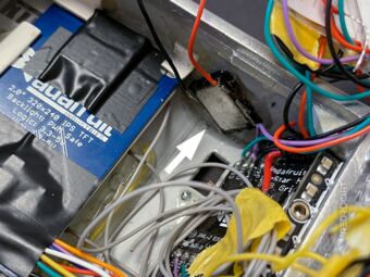
Right speaker (on the inside left) 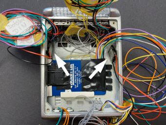
Both speakers on the side walls


During installation, I tested the speakers several times to make sure they still worked. The sound quality and volume of the speakers is quite good (also without sound holes in the shell and direct contact to the housing) – not high quality, but good enough for my purposes.
Note: Later, I had problems with the screen alignment due to the speaker position. The right speaker (inside left) should be positioned a bit higher so that the TFT screen can still be inserted/removed easily.
RGBW NeoPixels for the GEO-MET-BIO buttons
Section titled RGBW NeoPixels for the GEO-MET-BIO buttonsNext, I soldered a row of 3 RGBW NeoPixel buttons. To maintain proper spacing and reduce lateral light bleeding, I glued ABS profiles between them. After soldering, I connected the LEDs to my test rig and tested the LED positioning in the case. Then I electrically isolated the solder joints with more epoxy glue.
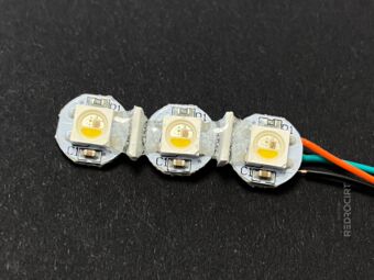
White ABS profiles as spacers 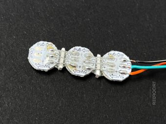
Solder connections on the back 
Positions of GEO-MET-BIO 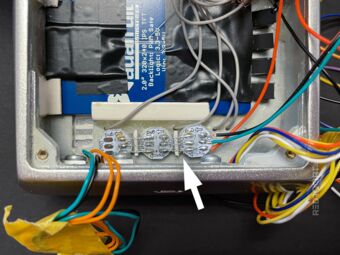
Simple fitting test (not yet glued) 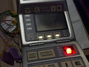
Function test before gluing in 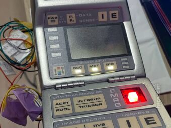
Function test before gluing in


Final installation of the USB socket
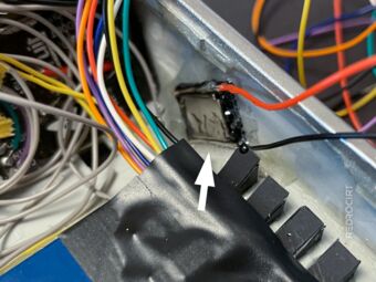
Section titled Final installation of the USB socketBefore I could glue the NeoPixel in permanently, I should first finish the USB socket to know if the two parts would fit next to each other as planned. So I soldered cables for +5V and GND to the USB socket and pushed it into the opening in the case. It fits in perfectly and is flush with the outside case wall. Since everything fit as expected, I attached the USB socket and NeoPixels permant with epoxy glue.
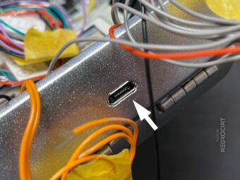
Inserted USB socket 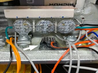
Wired USB socket fixed with glue 
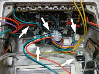
Glued-in LEDs for GEO-MET-BIO


Notice the green wire on the left in the last picture above. This is the NeoPixel data line connection to the NeoPixels inside the flap door. The green cable goes through the hinges.
Note: The NeoPixels inside the flap are powered with common +5V and GND that are also powering the touch sensor breakout in the door. I'm not sure if this wiring is correct. Perhaps I should have also made an additional GND connection directly between the NeoPixels in the main shell and the flap.
RGBW NeoPixels for the Alpha-to-Delta lights
Section titled RGBW NeoPixels for the Alpha-to-Delta lightsWhen I made the acrylic light guides, I had used an LED array of RGB NeoPixels for testing. At that time, this array fit well in the gap between the light guides and the side wall. In the meantime I have changed the plan and use only RGBW NeoPixel (with white light) everywhere.
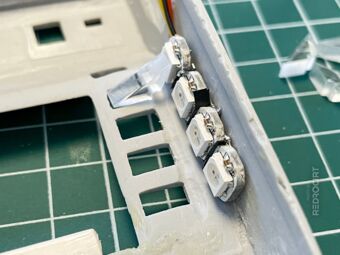
I tried to make a new RGBW NeoPixel array as compact as the previous RGB version, but I didn't succeed. The new array no longer fit in the gap. So I decided to disconnect the NeoPixels from the PCBs and reconnect them with cables. This allows me to attach the NeoPixels to the light guides with an exact fit and the separated PCBs will be placed at the bottom, behind the GEO-MET-BIO NeoPixels.
Old prototype, doesn't fit anymore 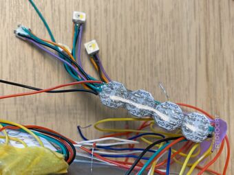
NeoPixels separated from PCBs 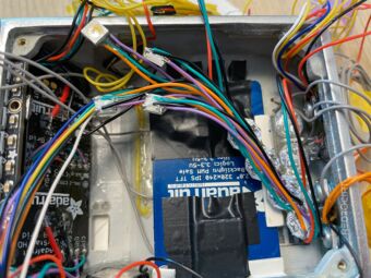
Rough test whether wire lengths fit 
First two NeoPixels in position 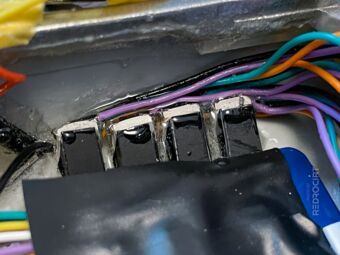
All 4 LEDs attached to light guides 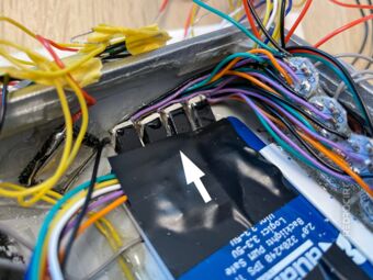
Alpha-to-Delta LEDs in place 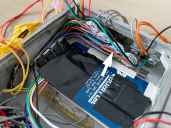
Separated NeoPixel PCBs 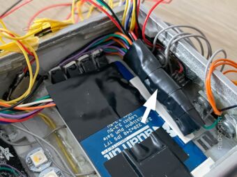
PCBs protected with insulating tape 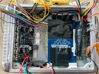
Interior view of the current state


RGBW NeoPixels for upper light positions
Section titled RGBW NeoPixels for upper light positionsThree more NeoPixels were missing in the chain: Two in the top row on the left and right, as well as one for the power button on the slanted inner surface. Again, I unsoldered the NeoPixels from the PCBs and connected them with cables so I could position them better. All three PCBs are positioned stacked between the upper LEDs.
All NeoPixels connected 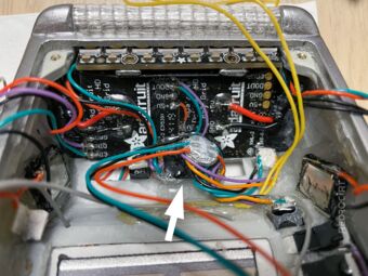
PCBs stacked in the middle 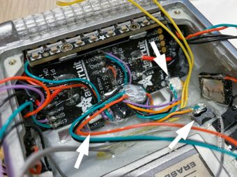
Separated NeoPixels glued in place


Updated NeoPixel chain
Section titled Updated NeoPixel chainThe chain of NeoPixels is thus complete:
- The stick with 8 NeoPixels (for the front scanner bar) will get connected to the RaspberryPi Zero
- The end of the stick is connected to the top 3 NeoPixels (just installed)
- The upper 3 NeoPixels pass the signal to the Alpha-to-Delta light row
- The Alpha-to-Delta array passes the signal to the GEO-MET-BIO button lights
- Then the signal goes through the hinge to the NeoPixels inside the flap door