After updating the diagram for my test board, I proceeded with the assembly (here is part 1).
Contents
- Breakout board arrangement
- Cable routing of the capacitive touch keys
- Positioning of the display wires
- Preparing the LED breakout board
- Installing the USB sound card
- Installing the rectangular LEDs
- Adding the capacitive touch breakout
- Installing the TPA2012 Stereo Audio Amplifier
- Adding insulation tape
Breakout board arrangement
Section titled Breakout board arrangementFirst, a small jump back in time, since I hadn't mentioned that yet: Before I glued the NeoPixel LEDs into the main shell, I had tried the arrangement for the next breakout boards.
- The largest breakout is the TLC5947 LED driver board, which is used for the classic rectangular RGB LEDs. This is placed on the left side (first picture below).
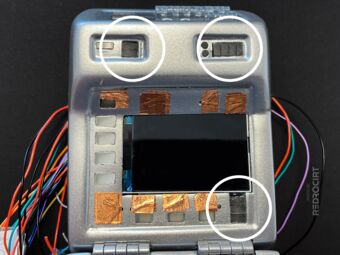
- Next comes the MPR121 capacitive touch breakout board for the touch keys in the upper main housing. This will be placed on the lower right side. In the picture below the 12 touch solder holes are placed on top, later I rotated the board to have them on the bottom.
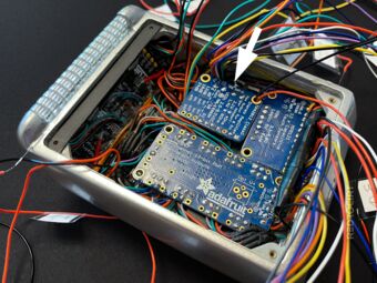
- Then there is the USB sound card and the TPA2012 Stereo Amplifier Breakout board to which the speakers are connected. The latter fits well in the upper right corner, above the touch breakout board. At first I thought that the USB sound card would fit next to the amplifier breakout (second picture below). But because of the many wires in this corner I later decided to put the soundcard in the top left corner.

Breakout boards above the TFT 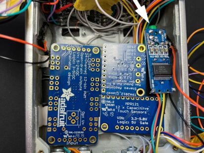
Discarded sound card placement


Cable routing of the capacitive touch keys
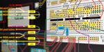
Section titled Cable routing of the capacitive touch keysTo make sure that all wires of the capacitive touch pads end at the solder points of the MPR121 breakout board, I routed the wires of the upper touch pads down along the side panels and fixed them with glue.
Wires along the side panels 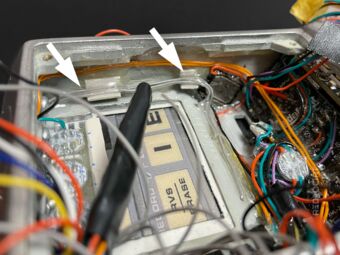
Wires above the TFT guide rails 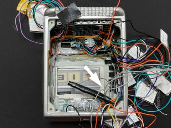
Meeting point of all touch pad wires


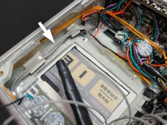
Positioning of the display wires
Section titled Positioning of the display wiresPreviously, I had temporarily added the TFT breakout with all the wires bundled at the top. Now that I had installed the resistors arrangement for the switches, this top position was already very crowded for all the wires. Therefore, I changed the cable routing of the screen once again so that they run sideways.
Note: At this point, I was still trying to keep the contents of the top section flat so I could insert the back lid with the pocket for the hand scanner. Later I gave up on that and used a lid without a scanner pocket.

Before: Wire bundle at the top 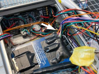
After: Wires exit sideways 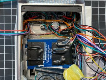
Inside view with the TFT breakout


Preparing the LED breakout board
Section titled Preparing the LED breakout boardNext, I sawed off a corner of the TLC5947 breakout board to place it further to the right while leaving room for the rectangular LEDs in the corner. I could not see any traces under the coating in this area, there was only the mounting hole, so it is not a problem to remove this part of the PCB.
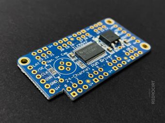
Sawed off one corner of the PCB 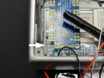
LEDs will be placed in the recess 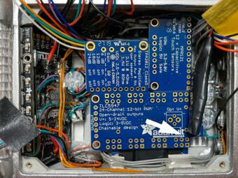
PCBs fit next to each other


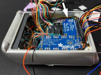
Installing the USB sound card
Section titled Installing the USB sound cardI removed the USB Type A connector and soldered wires to the PCM2704 USB Sound Card instead (first two photos below). Then I unsoldered the 3.5 mm headphone jack and soldered wires for the left and right channel to the board instead. These wires will later be connected to the TPA2012 Stereo Amplifier. To keep a flat design, I glued the wires to the sides of the PCB.
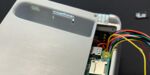
I decided to place the USB sound card in the upper area on the sloping surface above the reed switch and above the TFT screen. The PCB components are flat enough to later place the TLC5947 LED breakout flat above the USB sound card. Only the top of the LED breakout will overlap with the sound card.

PCM2704 USB Sound Card 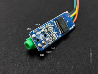
Determin the stereo channels 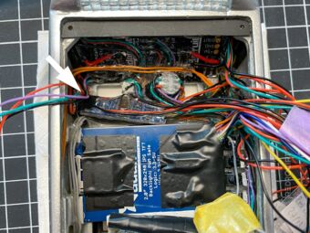
Sound card above top reed switch 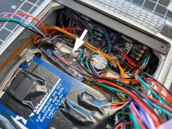
Placed on the inclined surface 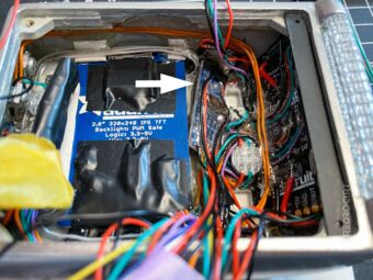
As flat as the TFT breakout height 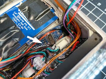
Epoxy glue for electrical insulation


Installing the rectangular LEDs
Section titled Installing the rectangular LEDsNext, I inserted the prepared rectangular RGB LEDs into the recesses provided for them. I determined the length of the wires to the solder holes on the TLC5947 breakout board, shortened the LED wires accordingly, and soldered them to the board. Handling the wires was a little tricky in this small space.
Added rectangular LEDs 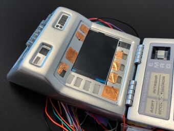
Main shell with all LEDs in place 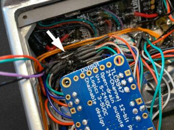
Wires of the top 4 LEDs 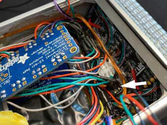
Wires of the top 2 LEDs 
Wires of the bottom 3 LEDs 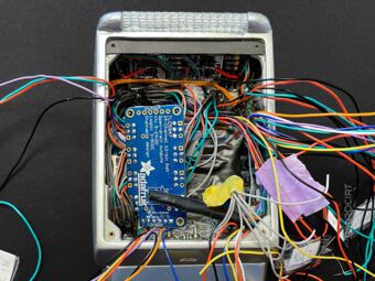
All LEDs connected to TLC5947


Adding the capacitive touch breakout
Section titled Adding the capacitive touch breakoutAfter all the rectangular LEDs were connected to the TLC5947 breakout board, I soldered the touch pad wires and data lines to the MPR121 capacitive touch breakout board (located at the bottom right).
MPR121 capacitive touch board 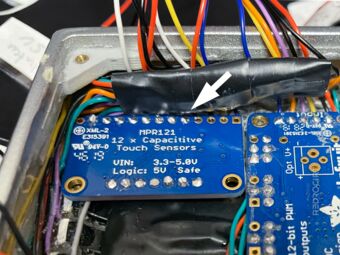
Touch wires soldered to the board 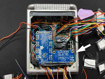
Positioned next to the LED breakout


Installing the TPA2012 Stereo Audio Amplifier
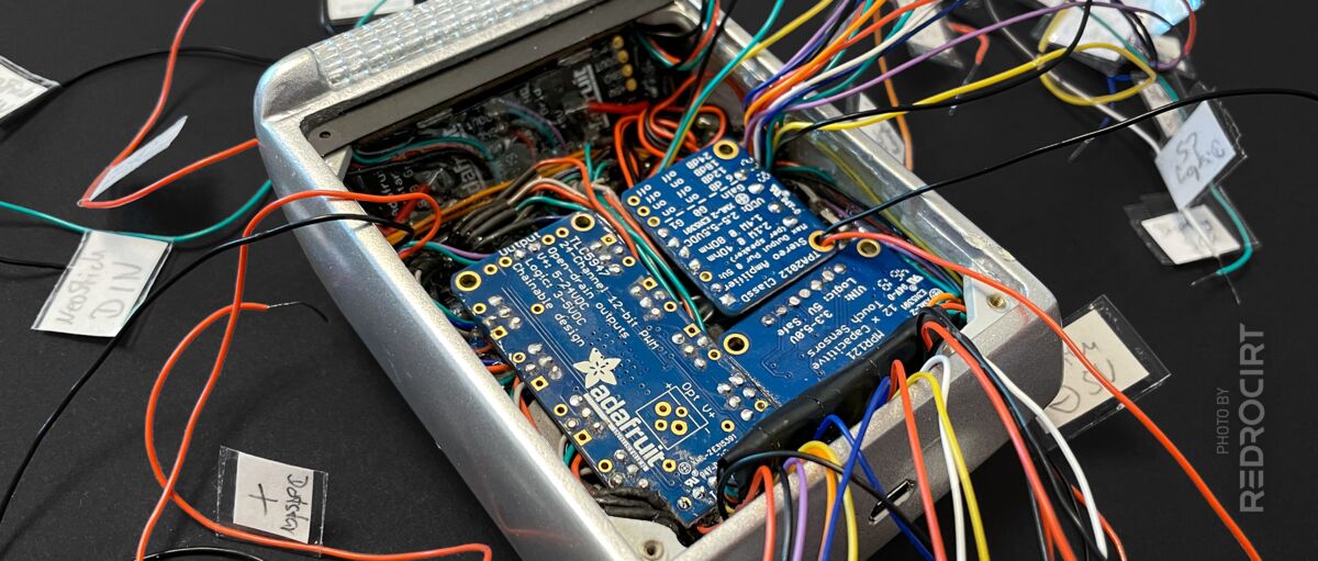
Section titled Installing the TPA2012 Stereo Audio AmplifierThe TPA2012 Stereo 2.1W Class D Audio Amplifier fit perfectly into the remaining gap next to the LED breakout board and the capacitive touch breakout board. I shortened the wires of the two speakers and the USB sound card (but left them long enough to remove the breakout board to access the gain switch) and soldered them to the amplifier.
Amplifier breakout board 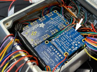
Gain switch pointing downwards 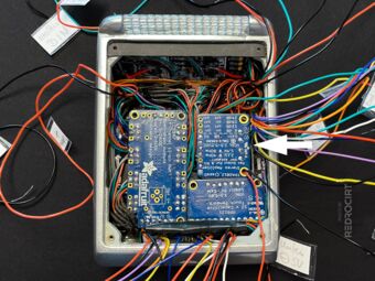
Final positions of breakout boards


Adding insulation tape
Section titled Adding insulation tapeFinally, I put insulating tape on the backsides of the breakout boards....

Protection of the solder joints 
Electrical insulating tape