To get the 2.0'' TFT screen flat into the body shell I had to modify the display cutout.
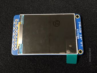
TFT display module 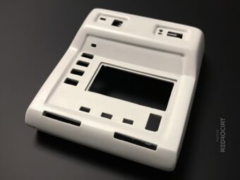
Body before modification 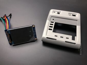
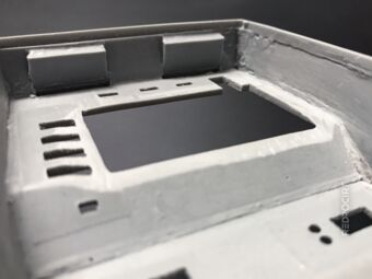
Body after modification


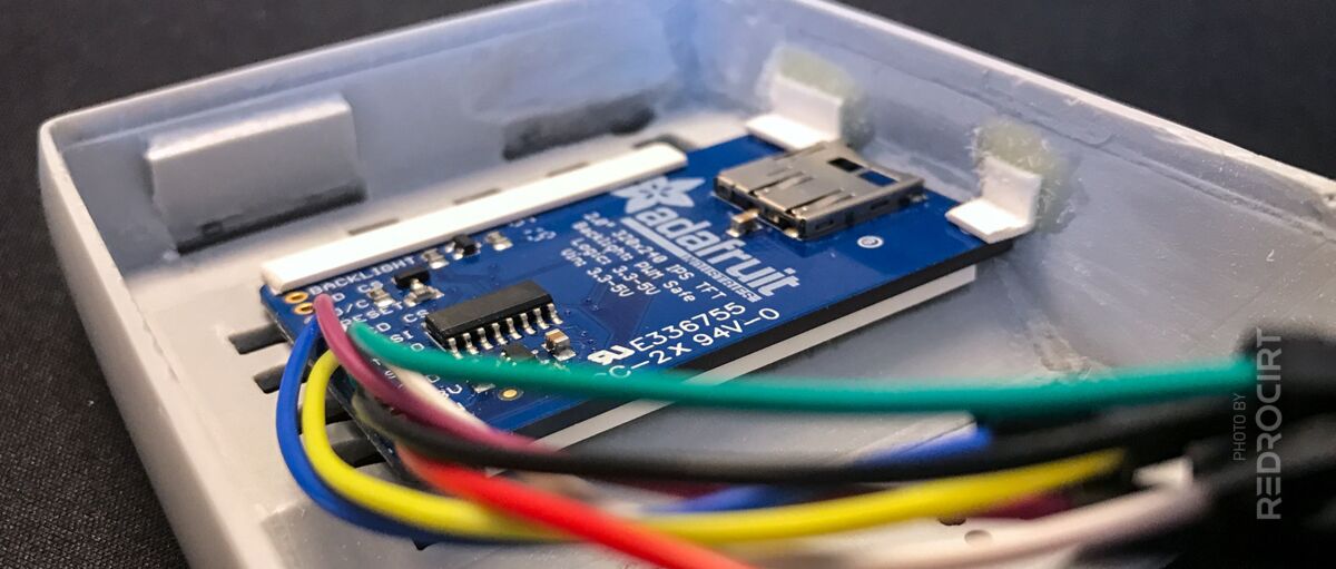
I carefully filed the borders of the display cutout to enlarge it. I also filed the resin shell on the alpha-to-delta light cutouts thinner to make room for the solder pads on the screen's board. I'm planning to use some self-made light guides for the alpha-to-delta lights. It will be a tight fit, but I'm confident it will work.
The screen's surface is larger in height than the shell's display cutout, so I also had to carefully file the top border of the display cutout to get a flat transition.
Enlarged display cutout 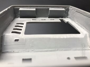
Flattened the top area 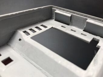
Flattened the LED section 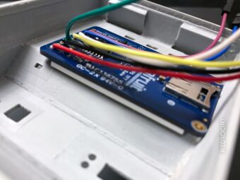
Screen protrudes at upper edge 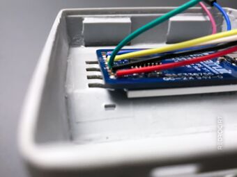
Solder pads overlap LED area 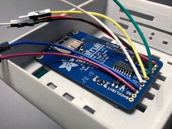
Screen sits flat in the cutout


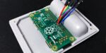
Inside the shell I used a high speed cutter with ball shaped head to carve the side wall next to the screen's PCB. The board has a SD card reader. I don't plan to use it at the moment, but maybe things will change, so I made sure it is still usable.
I wanted the display to be removable. It was already hold in place partly by the thin screen frame. I glued in small PVC profiles that serve as additional support so that the display cannot slip once it is inserted. To remove the display, I can simply push it carefully towards the upper end.

Short PVC profiles on the side 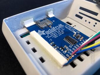
Wider PVC profile at the bottom 
The screen can be slided out


Unfortunately I forgot to take a picture of the other side at this stage. In newer articles there might be photos showing the display's front when placed inside the body shell...